Blog Archives

At last, a Finished Signal!
Well, that took a while longer to make than I had hoped! Not least because it is not the only signal I am working on at the moment.
Although the drawing did not show a landing in front of the balance weights, i felt that it was likely one would be provided given that these need maintenance at times. Hence this was formed from some L section and an etched slats and provides a useful point to secure the ladder too.
The issue with signals with dolls is that each doll is in effect its own signal; it has a ladder, arm and lamp assembly. But worse than this is that it is also necessary to get the movement to transfer over to the doll so there is even more than a seperate signal per doll. There are a number of ways the prototype used to get the movement to transfer and in this case the signal uses L shaped elbows. Sadly these are more challenging to make as there are more working components and to be prototypical they out to be little more than a couple of mm in size.
A key trick in making signals is to spray paint as much of the signal as possible. Because the components are generally fine any excess thickness of paint will quickly make the modelling crude. As a result of this, I now generally try to make the ladders detachable. In this case there is a rod attached to the top of the doll that a tube at the top of the ladder slips over, with prongs at the base.
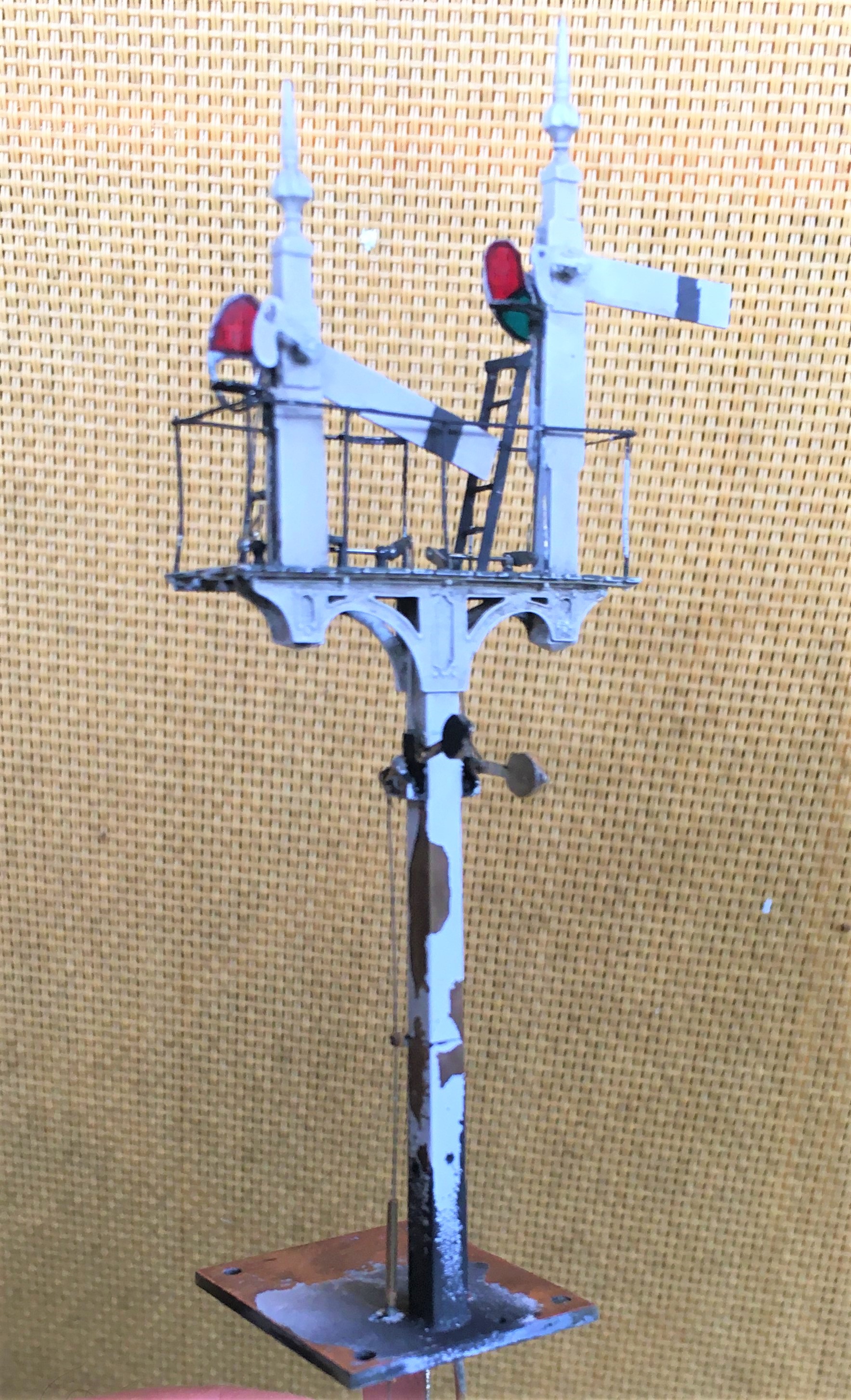
So here it is a finished (except for a tie rod which I fortgot to paint so is to be fitted shortly).
And as is de rigeur for a blog post on the building of signals, here is a video of it in operation.
")
More Seasons Greetings (and Signals)
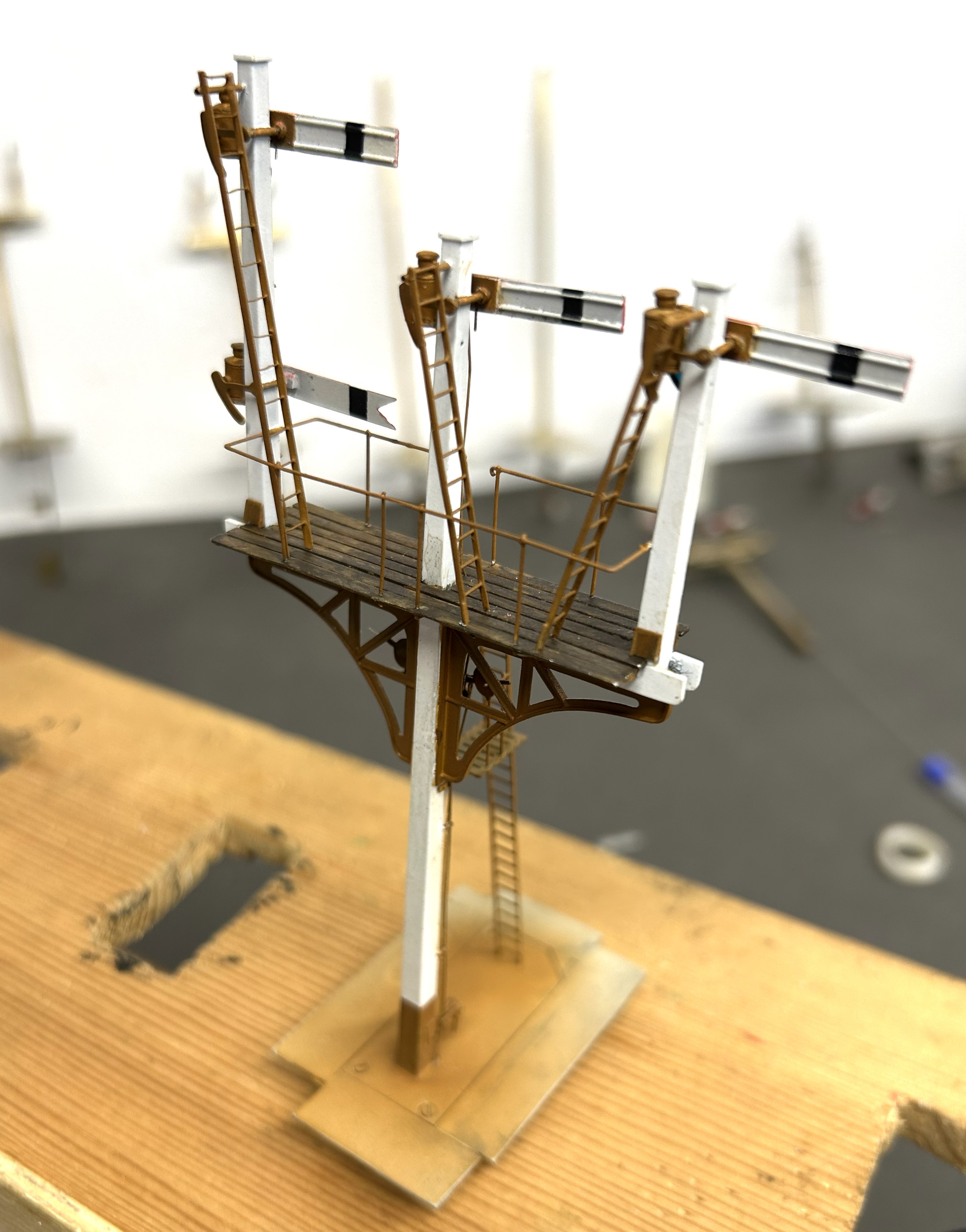
Having got the post and dolls in place, the next step was to fit the brackets.
The LNWR were unusual in not using cast brackets; instead they fabricated theirs from sheet and angle iron. Those supplied by MSE are a flat etch and therefore feel a bit one dimensional.
I therefore sweated on brass wire to one side of the strutts on both faces and also a plate on its outer edge. This helps give this a third dimension that was lacking before.

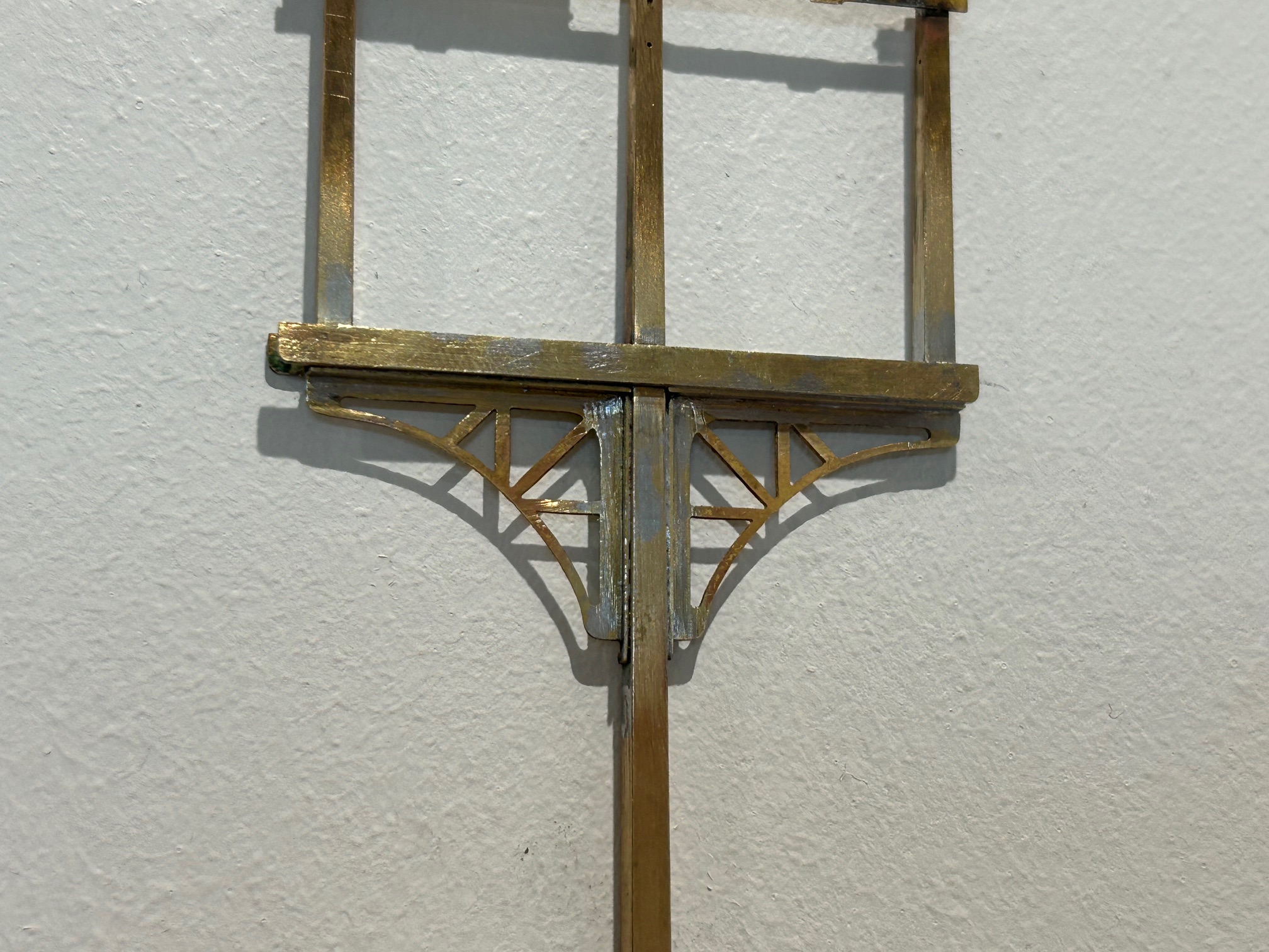
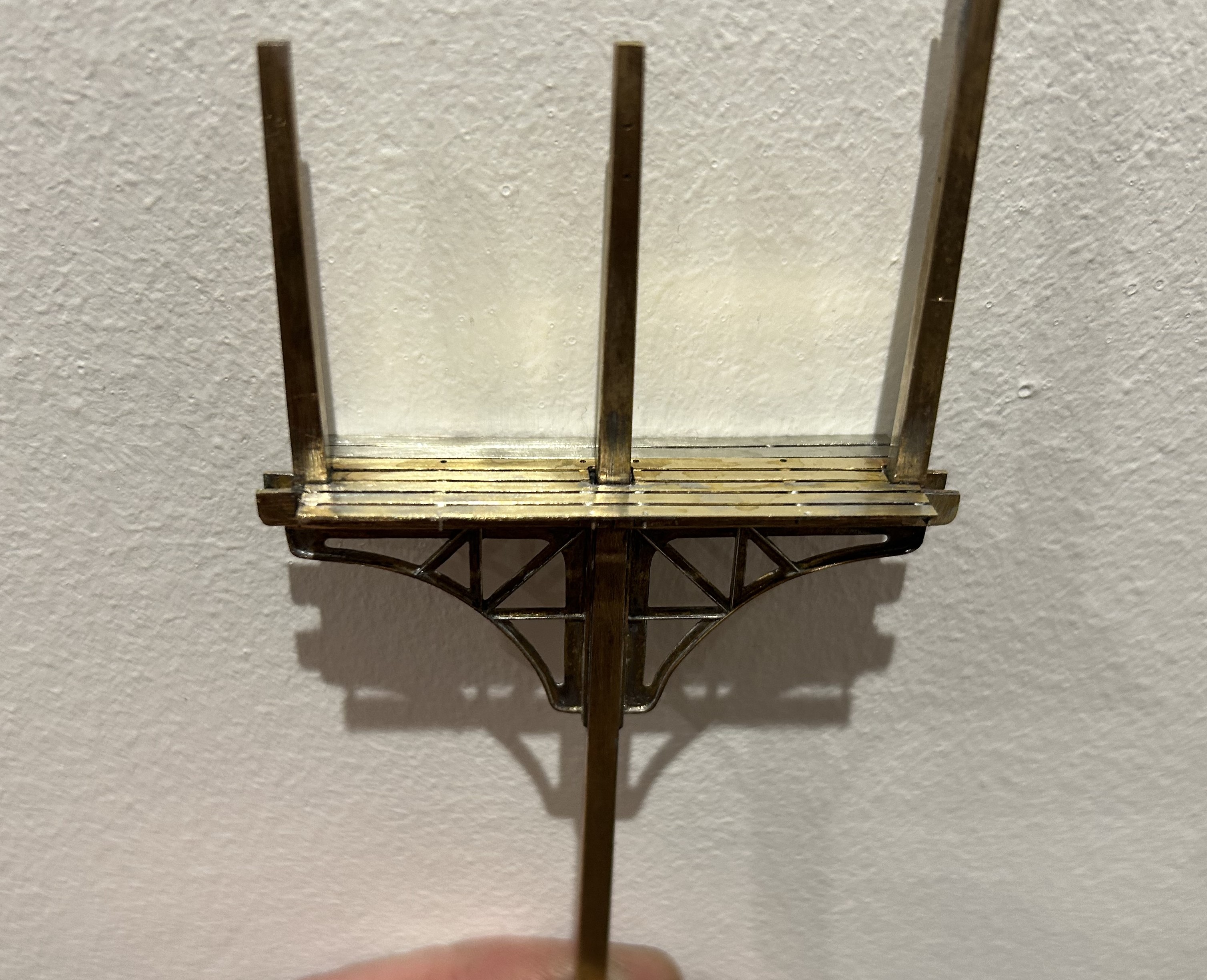
The next issue to be confronted was the landing where the MSE etch only provides a landing to the rear of the posts whereas this (and it appears many other LNWR signals) have landings both sides. I therefore had to produce support brackets and an enlarged area of landing. Foolishly, I forgot to drill holes for the guard rails before assembly, which meant that i had drill them in-situ. This is awkward due to the proximity of the dolls – it cost a couple of drill bits as a result and as a useful reminder to get it right next time!
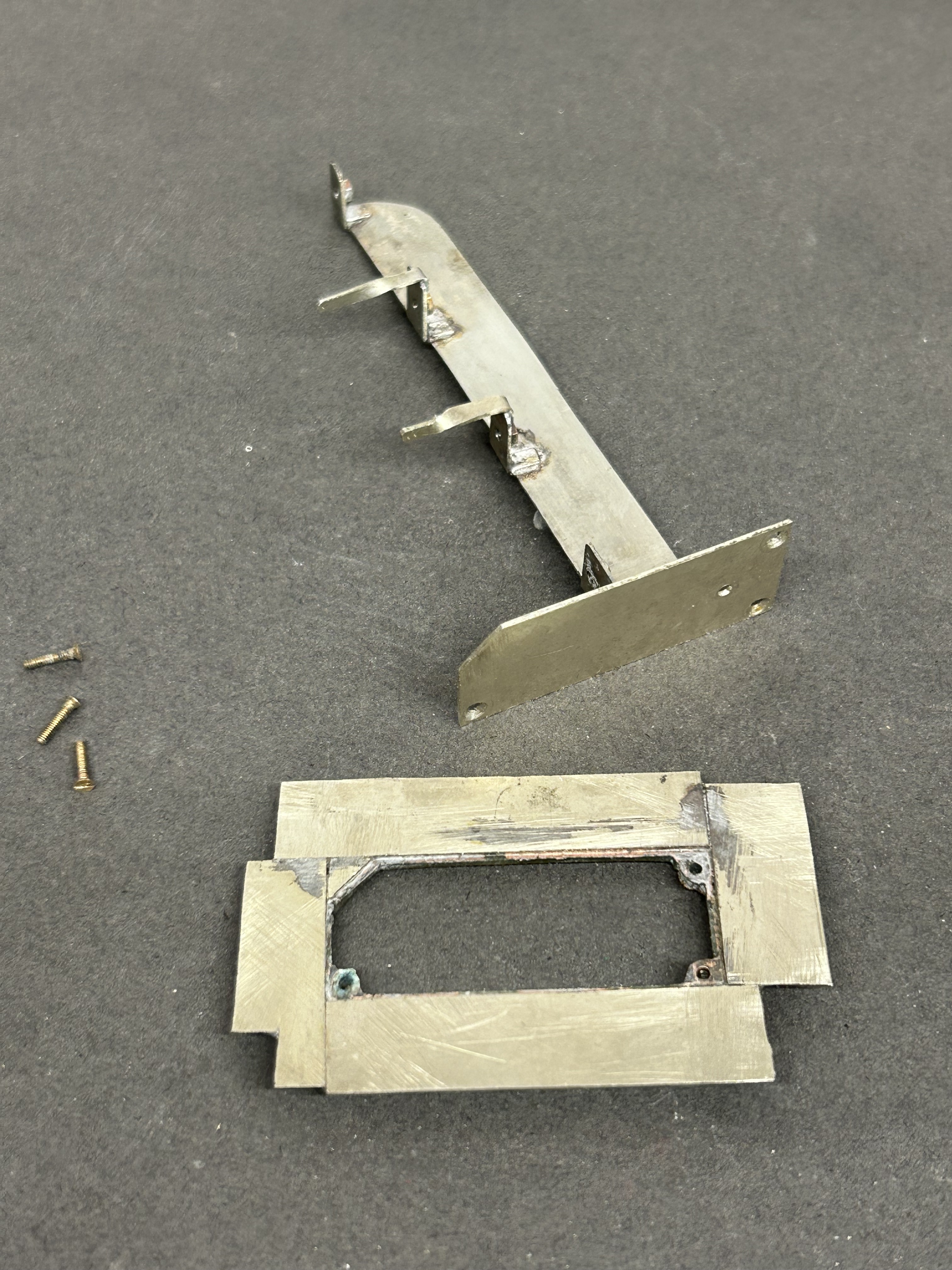
Next, I diverted my attention to the the mount for the servos. I now always form these with a lower base which is permenantly attached to the baseboard and into which a second detachable base plate is inserted. The two are a tight fit such that once a little scenary is applied to the top, the joint is invisible. These are secured together with 12BA screws to allow it to be detached both during the build and for maintenance but generally it is secured in place. This is because signals are prone to damage when being moved about and would need recommissioning to get the movement correct each time they are reinstated.
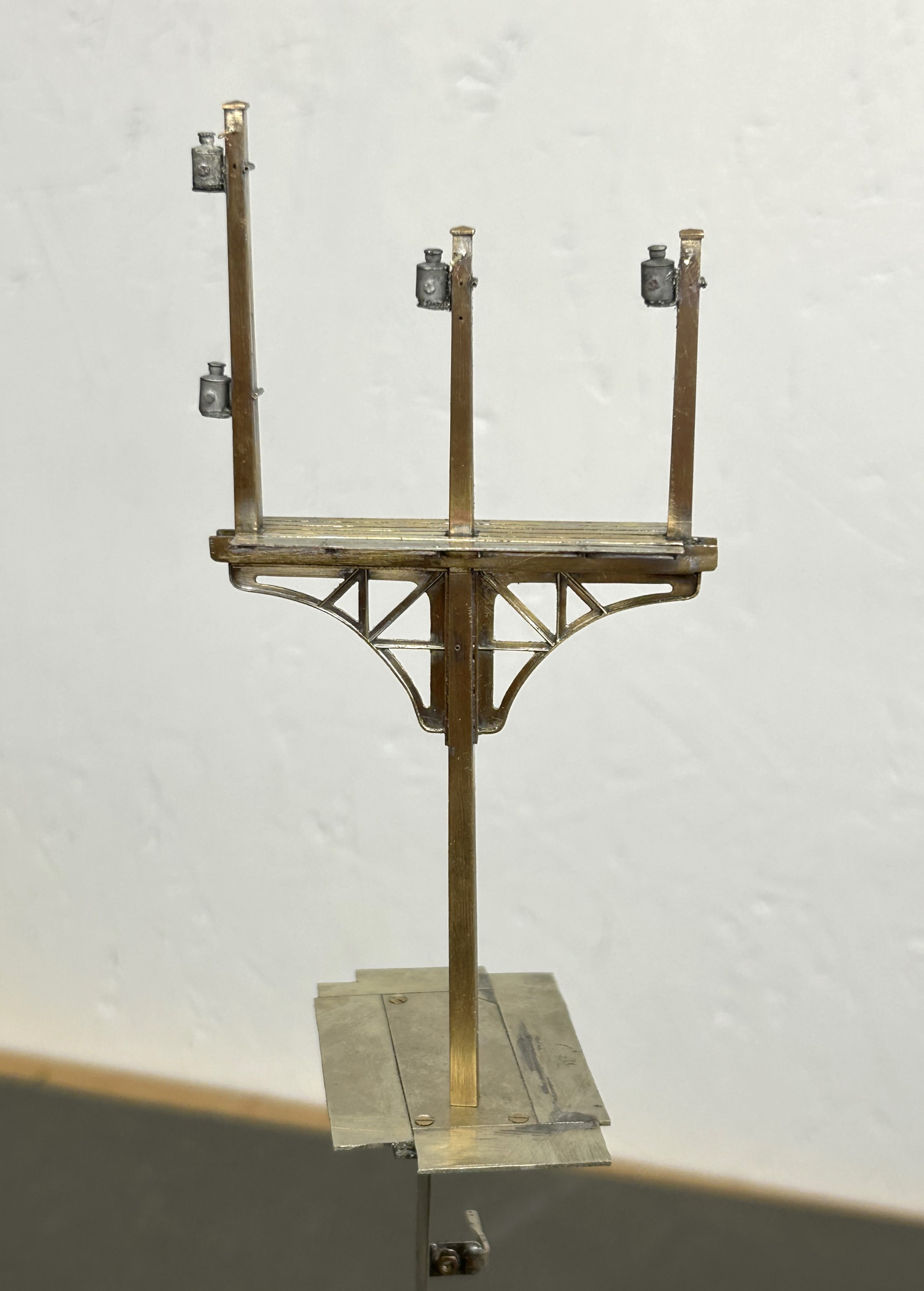
I drilled the underside of the post and tapped it 10BA in order to hold it in place. This enables me to secure it onto the base but subsequently remove it as I build it. I do solder it in place at the end of the build, but the ability to remove it during the build is helpful. The fact that the bolt holds it in place also makes it easier to get the post vertical, rather than trying to hold it vertical simultaneously with the soldering.
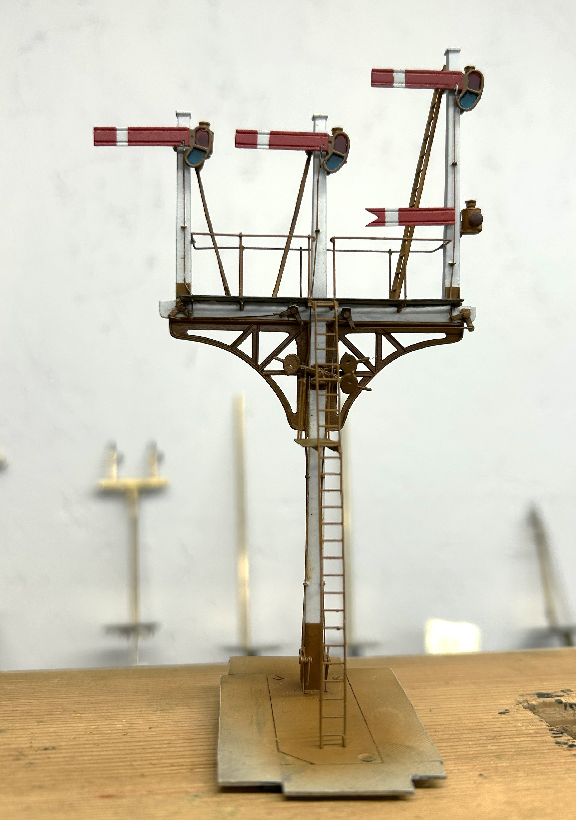
Whilst MSE do provide a white metal casting for the finials, I opted to fashion my own with brass as I find them crisper. To ensure these do not fall away as later tasks are completed, I use a high melting point solder for these and also include a pin drilled into the top of the post. Lamp brackets, lamps, the balance weight mount and some supports for the ladders were next.
I now have a recognisably signal beginning to form but the difficult bit, the movements are still to go.

What Have I Been Doing…………..?
Gosh, another year where my intentions to increase my rate of posting have got away………..
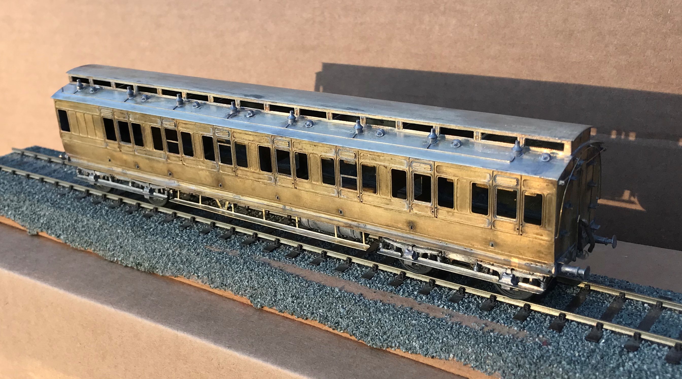
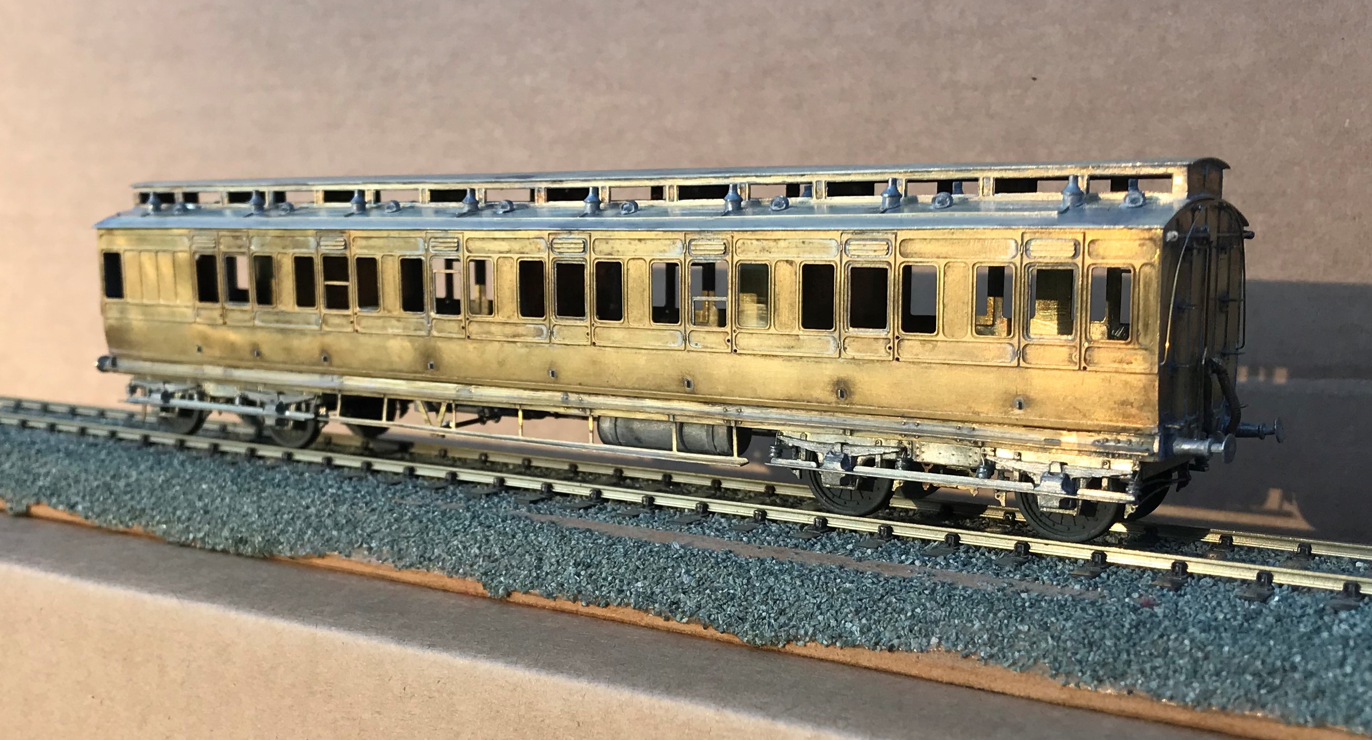
Whilst work and home life have intruded, I have still managed to get some modelling done; including a rake of NER coaches for John James for which i do get something in return in due course.
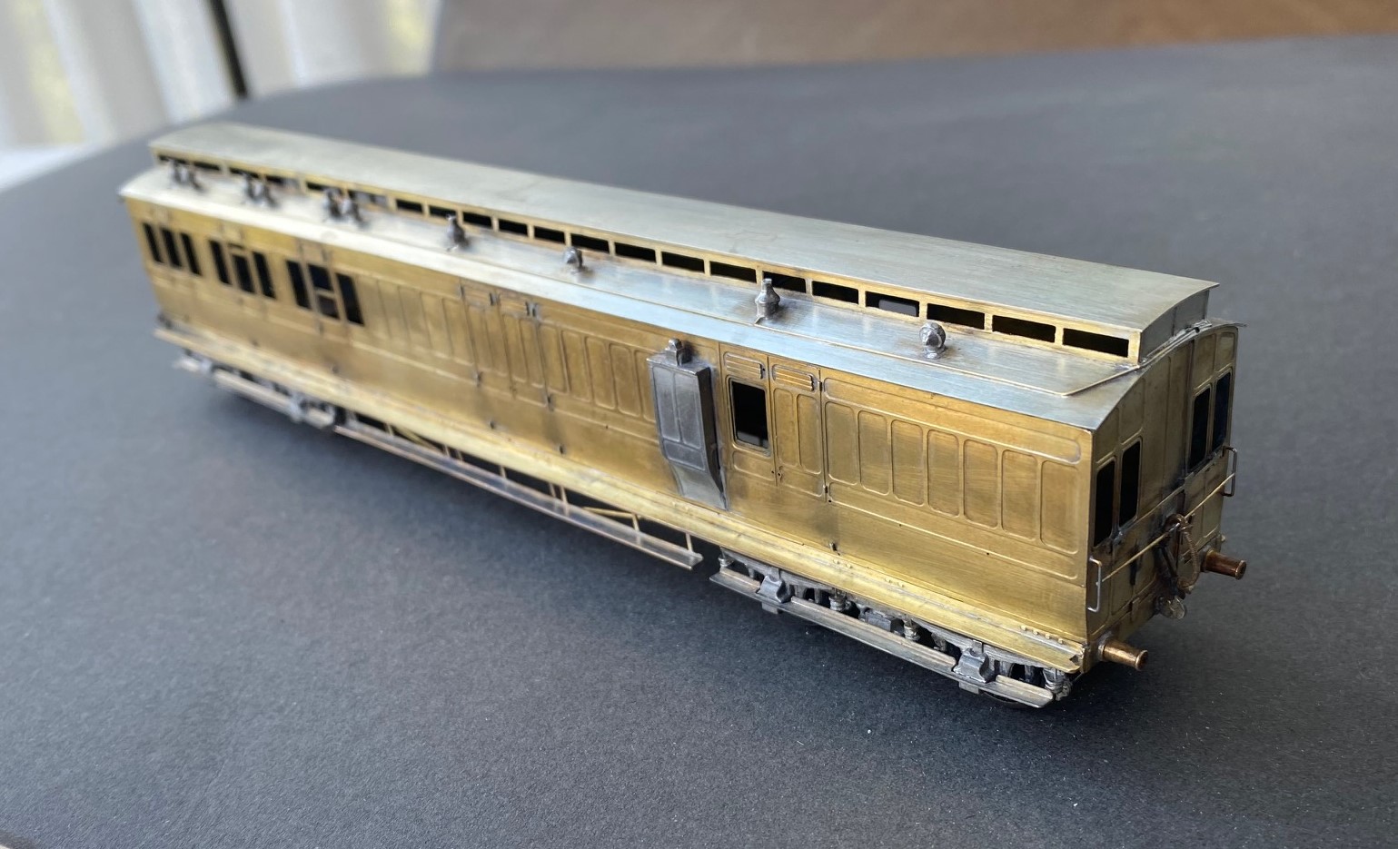
The rake had a pair of three compartment thirds, of which this is an example:
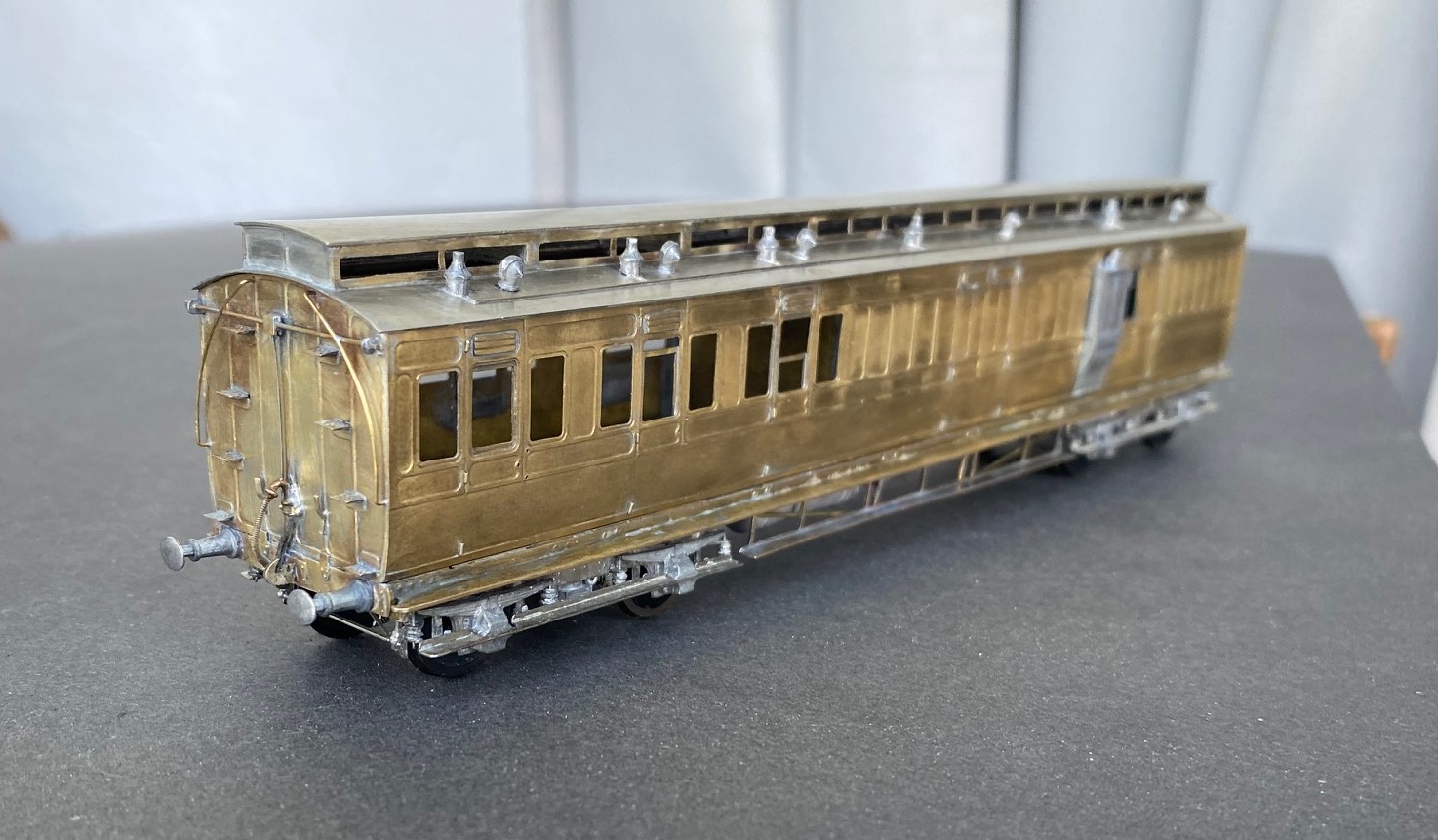
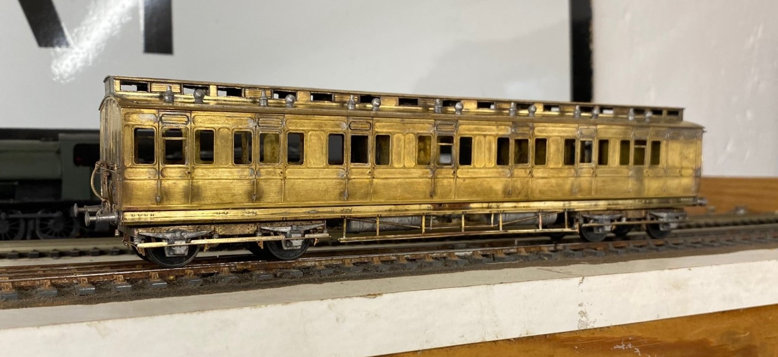
All of the coaches were constructed from D&S kits on my Miscellany Models Fox bogies with replacement roofs formed of nickle silver sheet. I find that the plasticard offering in the D&S kits to be their weakest point. The problem with this is that if you make your own roofs i find you might as well also cut out the section below the clerestory – it makes a huge difference for the coach to be illuminated from above. The issue is, that there is a lot of work in these roofs – I found that for each there was 15+ hours of work just in the roof!
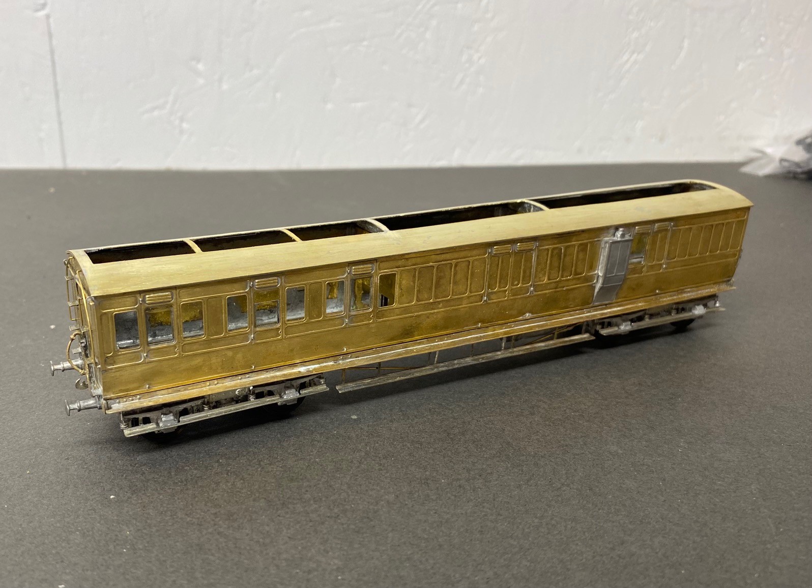
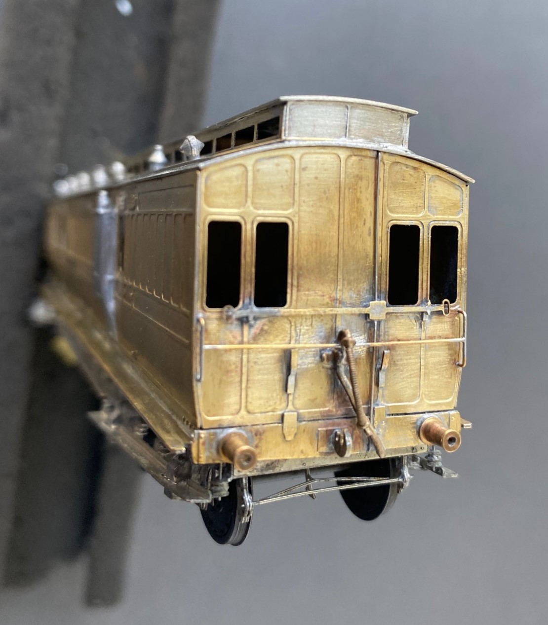
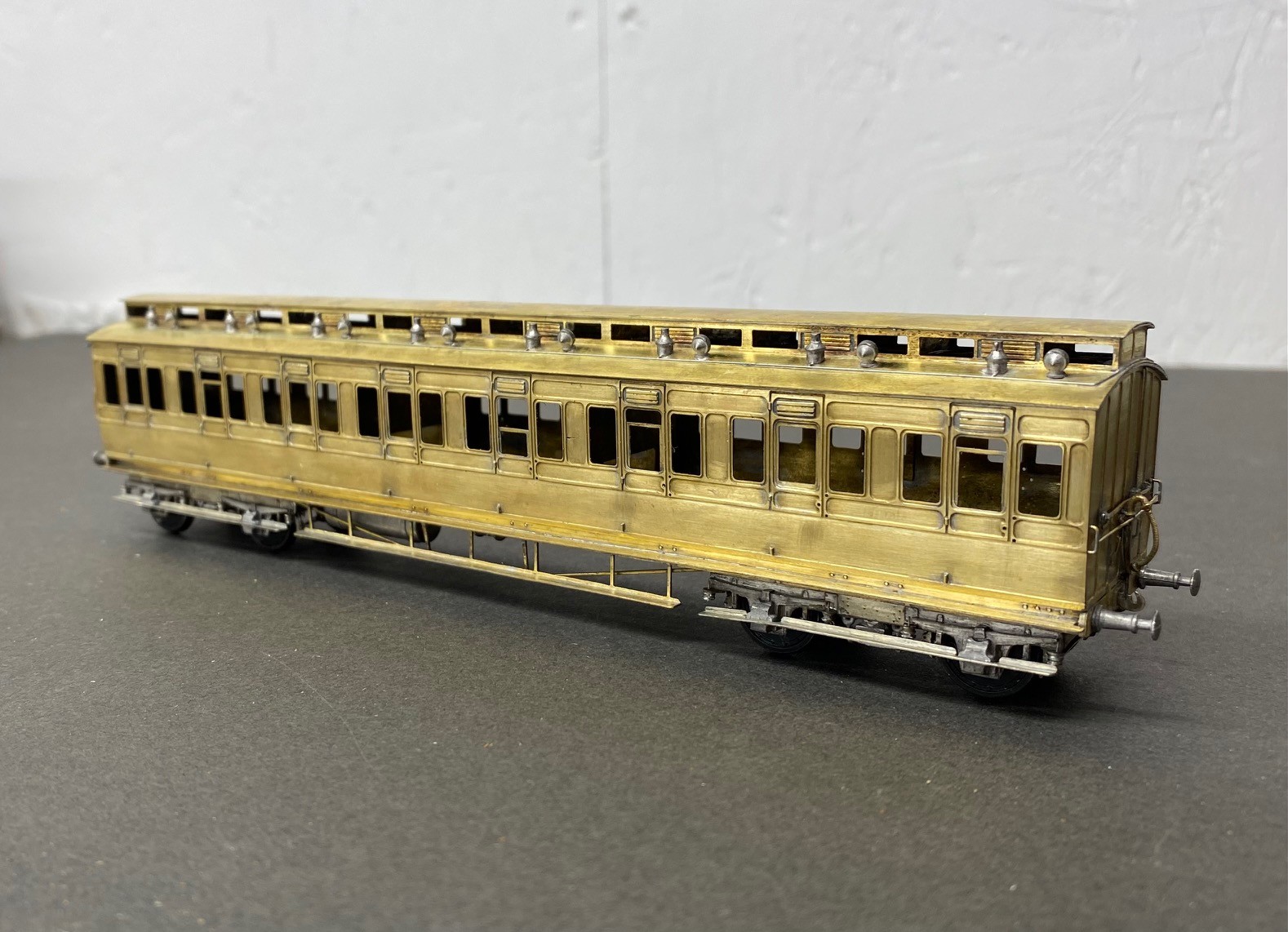
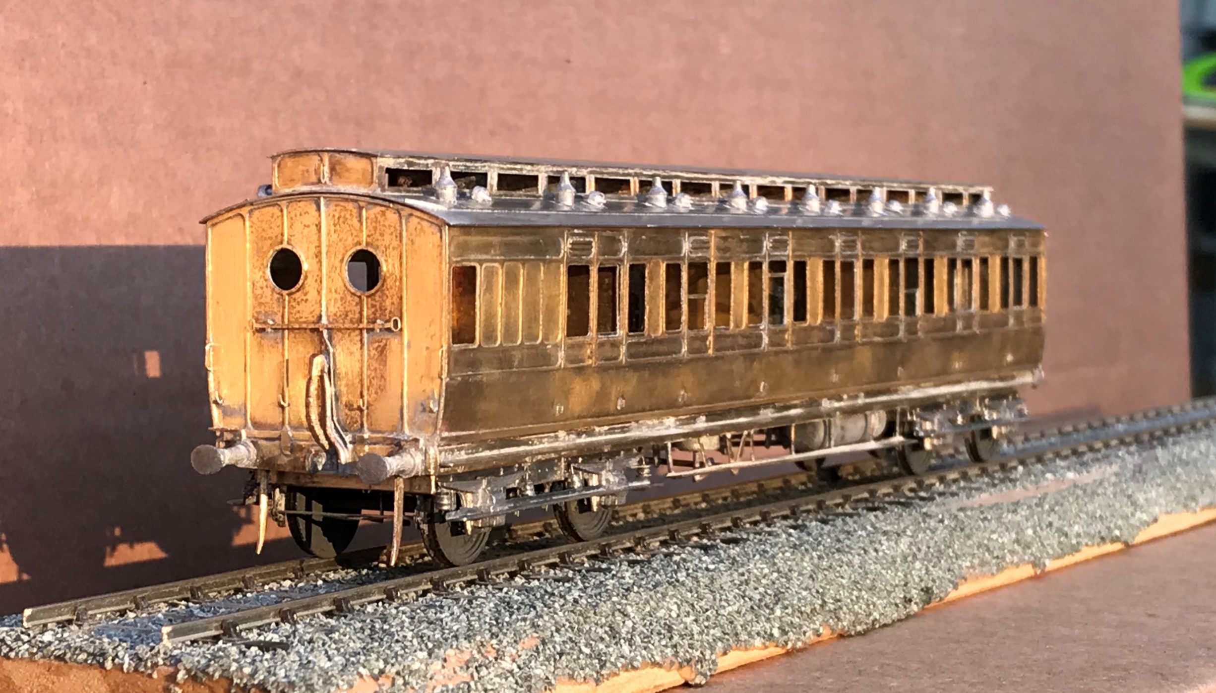
Also in the rake is an all third, which is probably my favourite of the build as it feels quite “pure” and also wihtout the problems of the composite…….see below…….
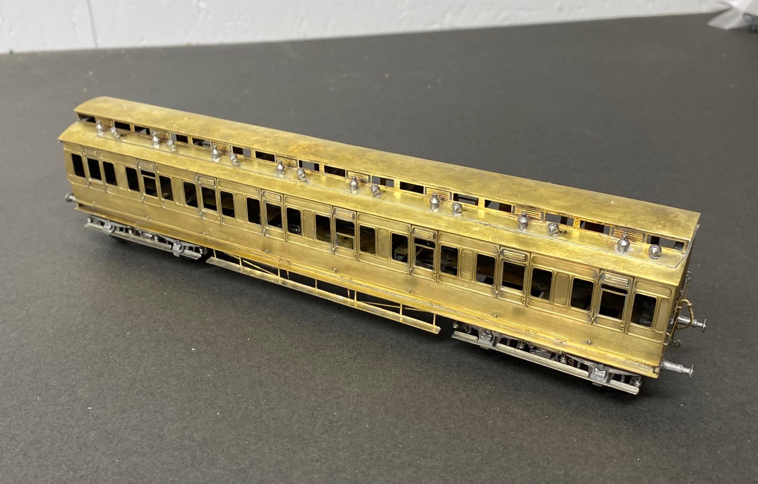
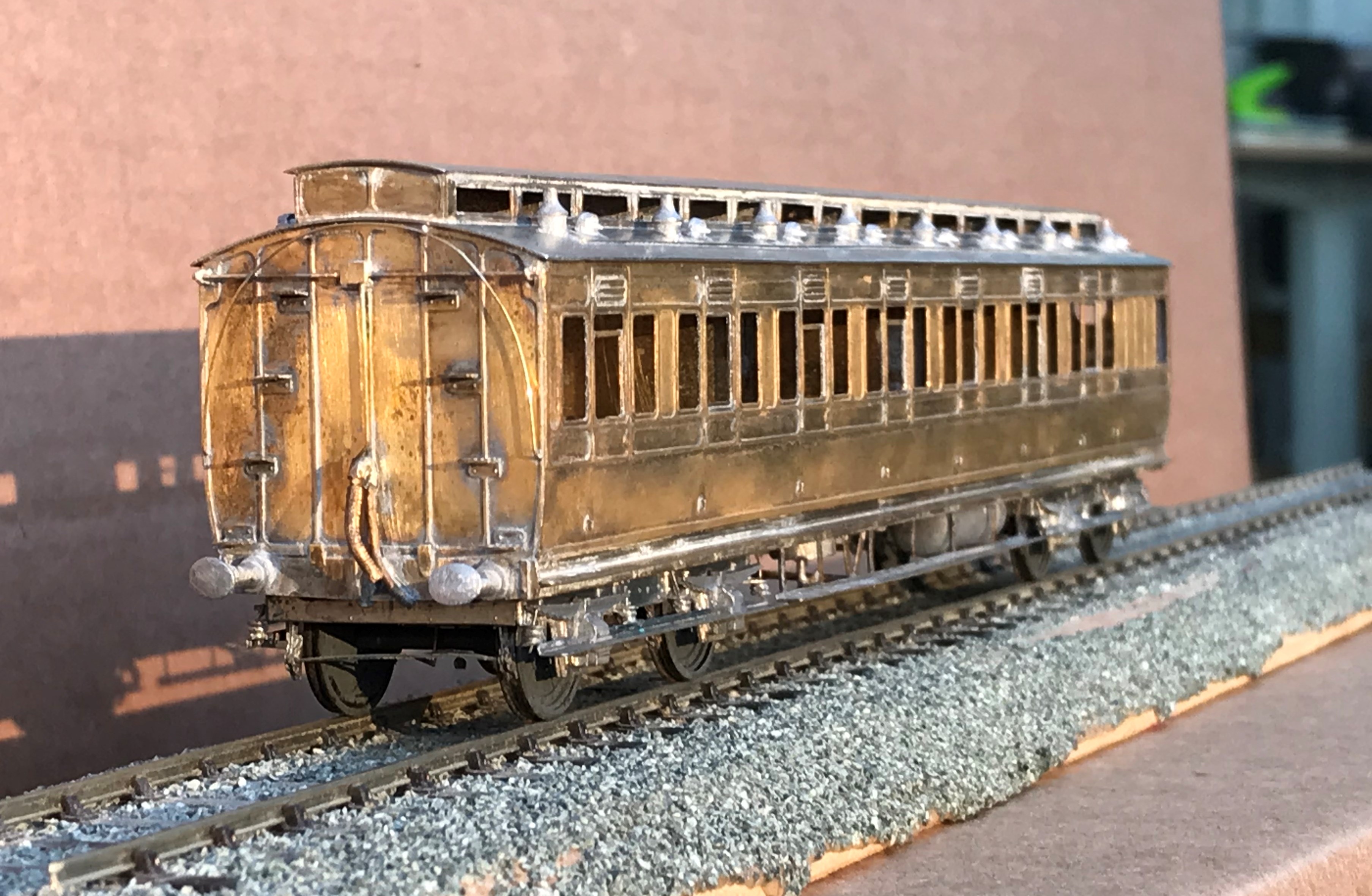
The rake only needed a modicum of first class accomodation made up from a composite diagram 7. Alas, this had a challenging problem that needed to be overcome, with the clerestory side pieces. These were much shallower than those on the other kits orwith the ends supplied in this kit. In addition to being obviously incorrect given the inconsistancy but the frames around the glazed lights were stunningly delicate. I regret persisting with this, i should have just drawn up some replacements in CAD and popped them in the next etching order.
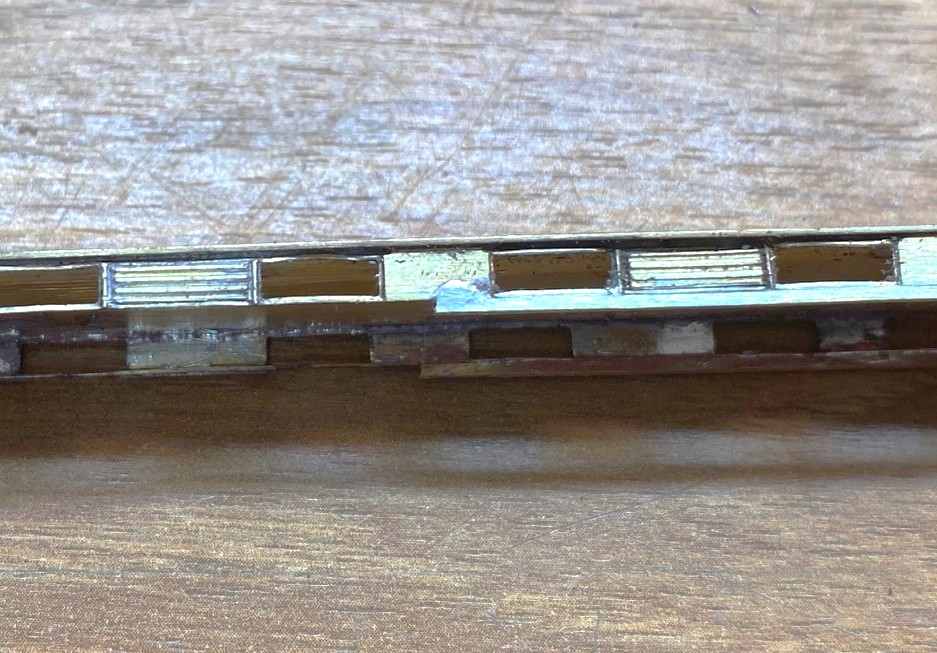
However, i solved the problem by soldering a flat strip, 1.5*0.5mm along the base. in theory it should be to both the top and bottom but that was not realistically possible and I decided life was too short. After much fighting, cussing, fighting, screaming and more fighting, I did get it there, as I hope you can see.
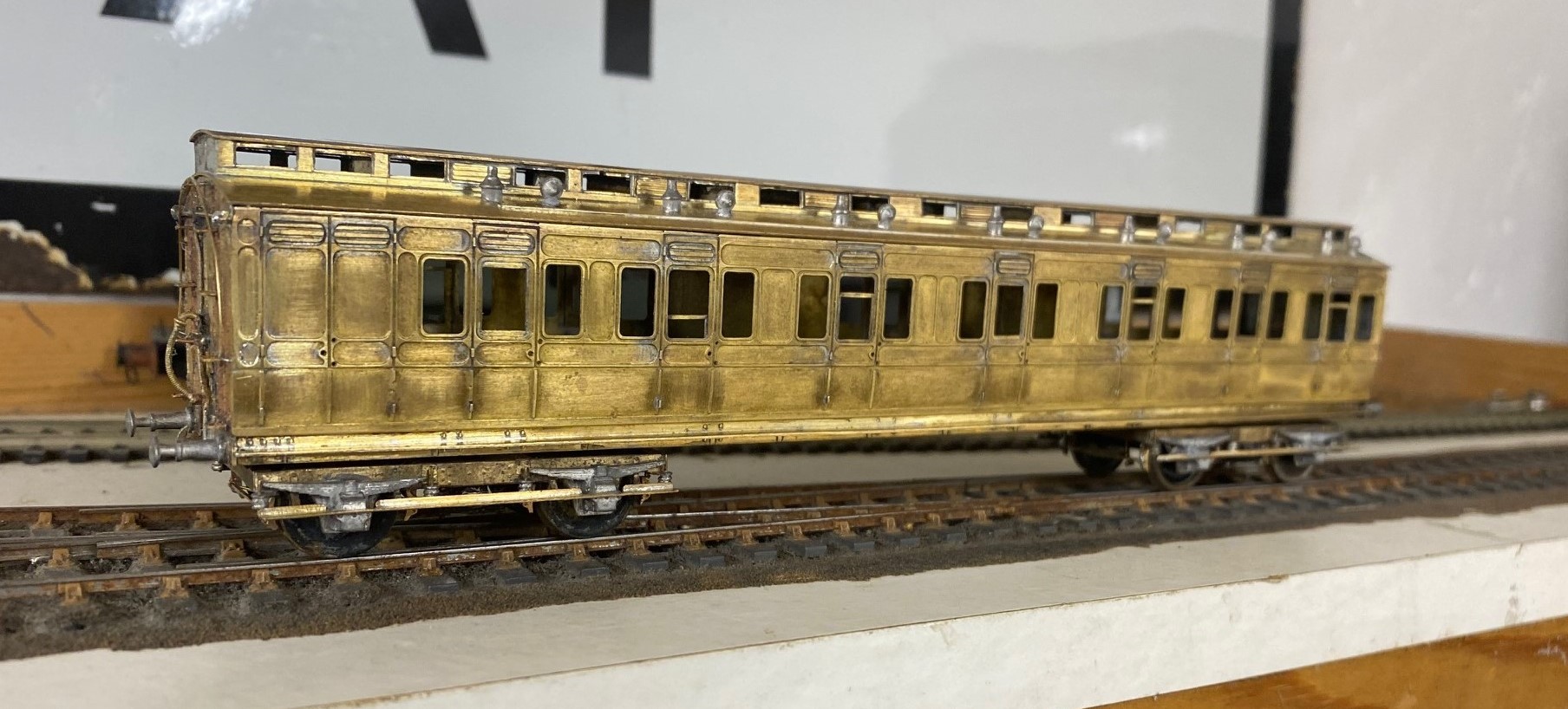
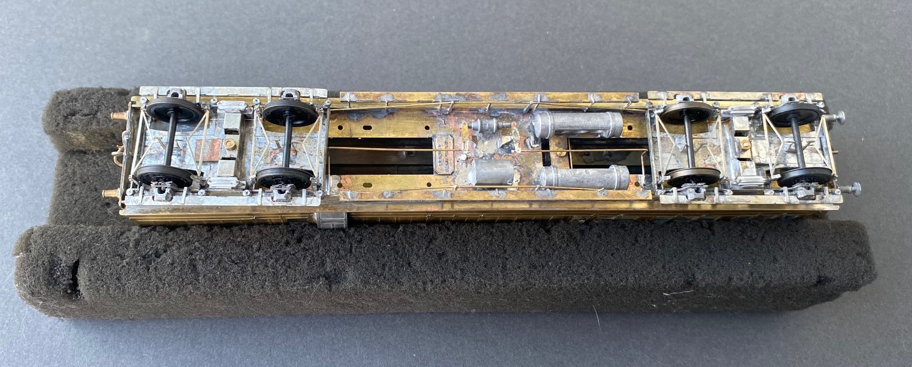
I was asked to do these as gas lit coaches and therefore there is a bit going on below, as one might say.
As the coaches were quite long lived, they went through many detailed changes. for anyoen who is contemplating building some, I would heartily recommend reading David Addyman’s notes on how he built his in the Scaleforu Forum https://www.scalefour.org/forum/viewtopic.php?f=39&t=7210&p=101662&hilit=ner+coaches#p101662 David’s coaches are modelled in the 1930s, so have different lighting arrangements, footsteps, bogie spring dampers and sides to the clerestories. Lots of things to be aware of if you are doing something similar.
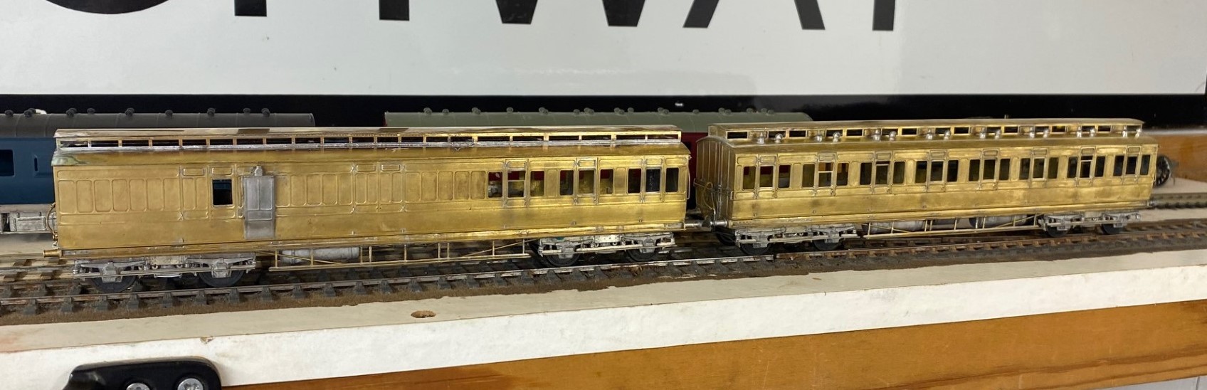
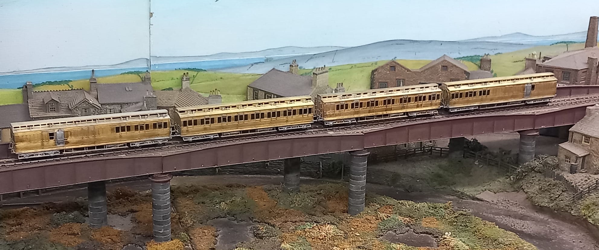
At the end of this rather mammoth build, I had four coaches that i was rather proud of. They look rather fine on John Wright’s Benfieldside viaduct.
I am also pleased that i do not have to paint these; i am still looking for my lining mojo. I had it as a teenager, but have grown shy of lining. Maybe something for the Christmas break?
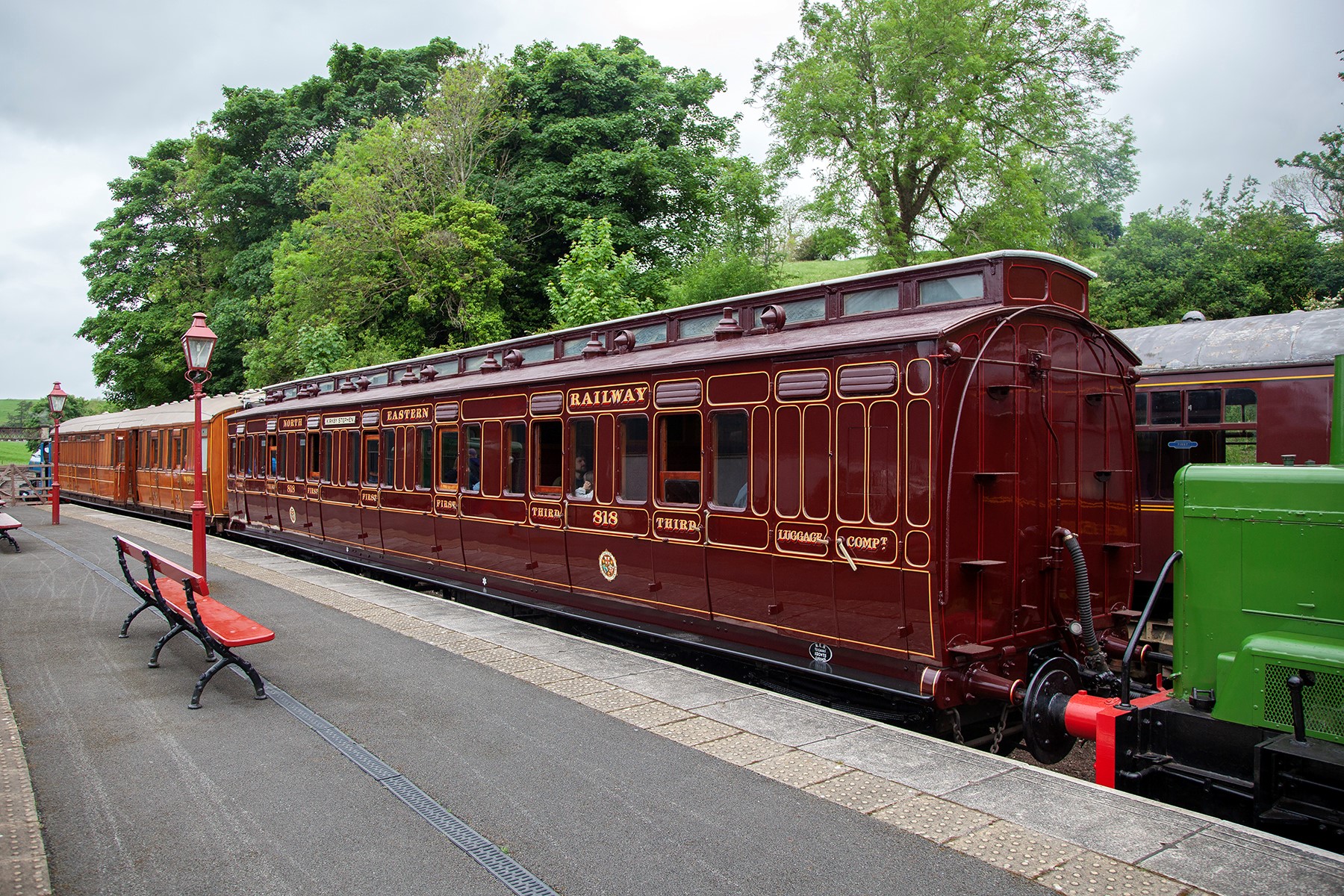
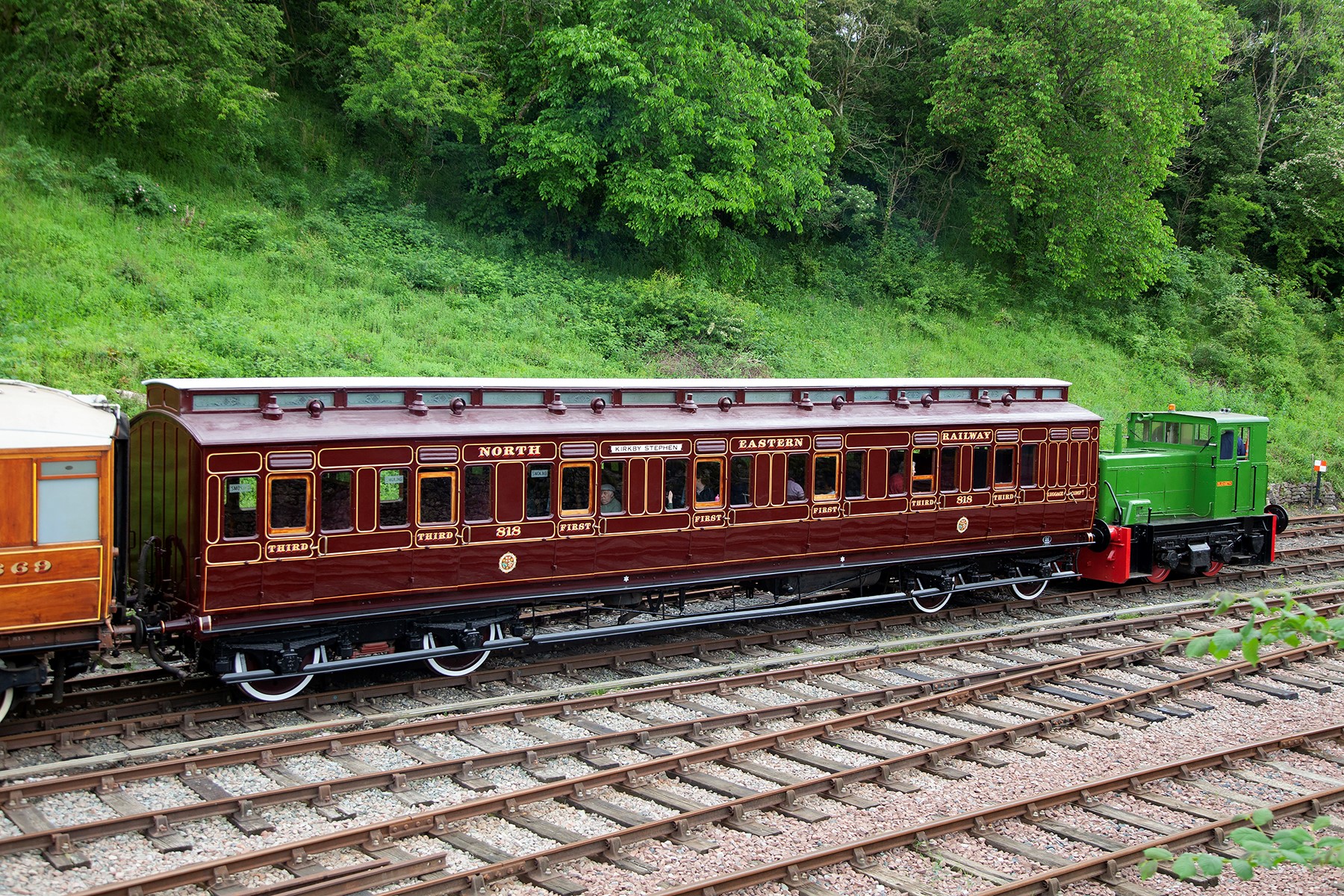
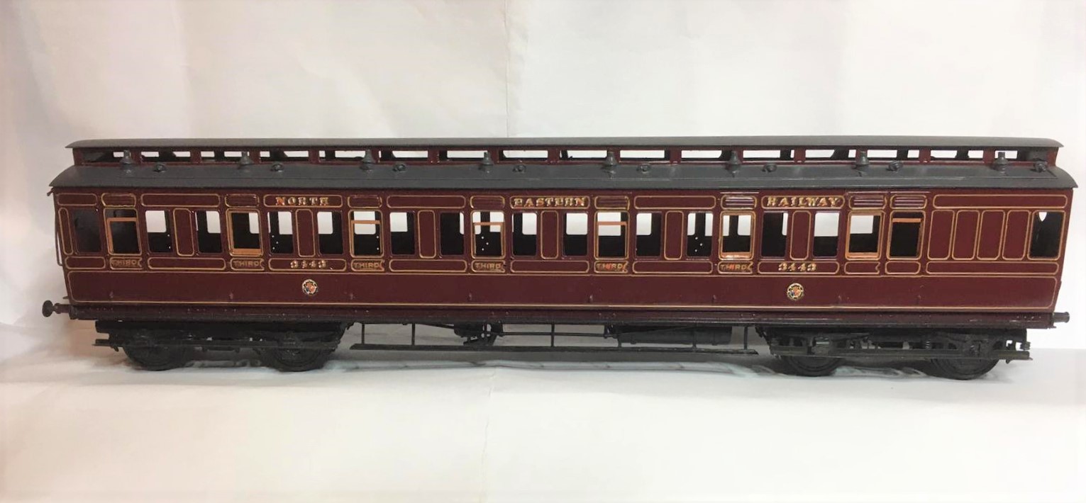
In the meantime, here are a couple of pictures of the newly restored NER coach 818 at Kirby Stephen, courtesy of the Beamish website. Does’t she look magnificant? I really must get up to see her.

Still Swapsie – A Signal for Nampara for Hendrawna Part 2
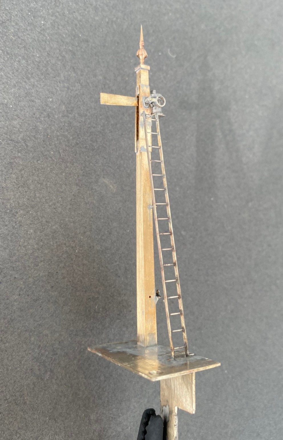
Having assembled the basic post and ensured that it was working, the bolts can be filed away and we get to the following stage.
The spectacle plate plate is rather unusual in that it only has one lens which isn’t available via any manufacturer and the arm is notably shorter than I am used to so I had to etch these to suit. Although I could not find a lamp that matched what was on the prototype, I was able to modify a MacKenzie & Holland lamp from MSE to suit. Thereafter, the remaining assembly of the signal was fairly unremarkable.
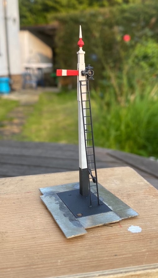
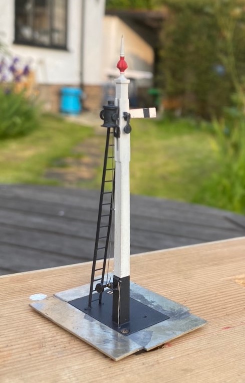
And then once it had been painted, including the unusual red highlighting on the finial that I rather like:
And of course we must have the obligatory video to show that it really does work!
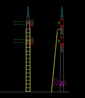
And for those of you that might want it, this is the drawing of the signal, which has two arms, at Didcot.
Swapsie – A Signal for Nampara for Hendrawna (Part 1)
Swapsie – the childish act of swapping things according to Wiktionary.
Do you remember at school swapping a Top Trumps set for a the latest Hot Wheels car or similar? I do! I remember getting roundly b*llocked by my mum for not recognising the value of things I was giving away and (metaphorically I am pleased to say) swapping gold bars for glass beads almost like the Incas and Cortez.
In the world of toy trains, the same happens and is very useful where someone can offer something that you don’t have (or find difficult to make) in return for something you do have. This is one such example. Sitting next to Duncan Redford at an EM Gauge Society/Scalefour Society skills day a few years back demonstrating signal construction a barter was arrived at whereby I would build Duncan a signal in return for him doing some 3D design and printing. I think it is fair to say that neither of us have rushed with our respective shares of the bargain but with the next ExpoEM only a week away, I have shifted into gear to finish the started signal that was my part of the deal.
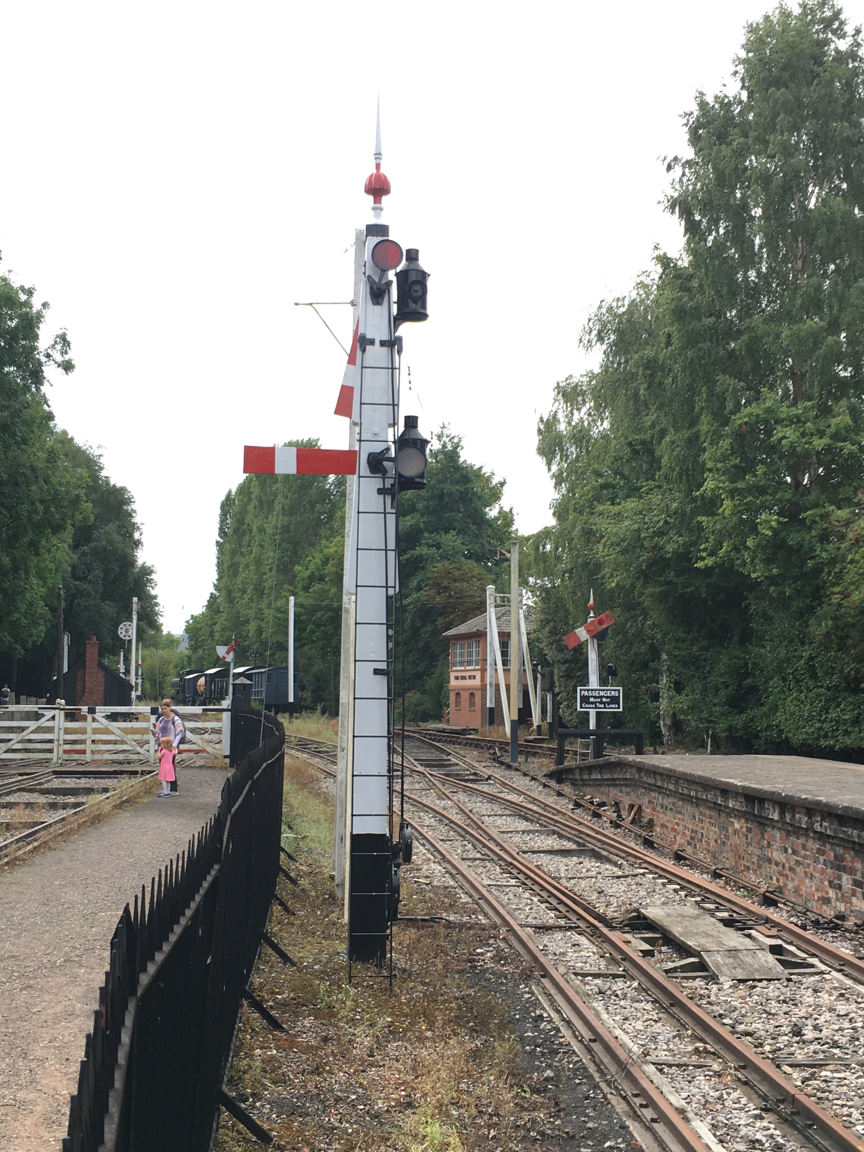
Duncan is building a GWR broad gauge era layout and wanted a close replica of a signal that the GWR Society has recreated at Didcot, but adjusted to have only a single arm. So after coming out in cold sweats about the idea of modelling anything GWR (!!!) I took a look at it. Like many signals, there are differences and similarities with other signals but after a bit of study it became clear that it was sufficiently different that a site visit to Didcot to be required.
Having measured it up including, when no one was looking, a climb to the arm/lamp to measure it, I came home to draw it. I was shocked to find that it was tiny; 3mm/1foot at best and I had a panic attack -had I mucked it up and mis-measured it. Obviously, being a professional surveyor I could not possibly have done that, could I? After a few months, the fear that I had niggled on me and so came about site visit number 2 and a further climb up the signal ladder. Nope, it really is tiny – both the post and the arm are notably smaller than I am used to.

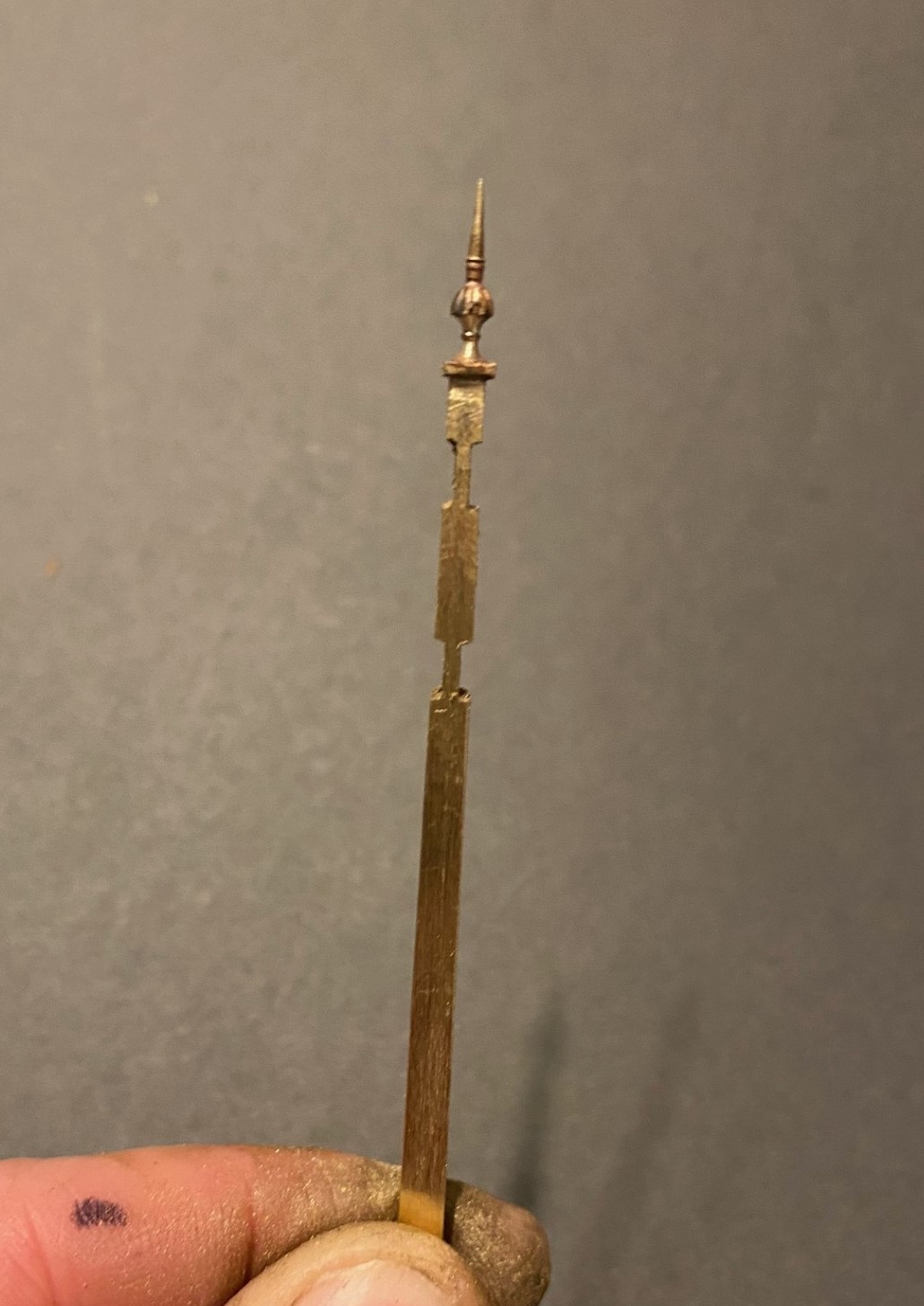
There are several unusual aspects to the signal; the one glass spectacle plate, the tapered arm and the very pronounced stiffening around the slot in the post were all going to be key to capturing the character of the signal. So out came the computer and a small fret was added to an etching order for the arms/spectacle plates. I then formed the basic post from 4mm square section brass which I filed to a taper with a 2.5mm cross section at the top.
Despite having built a few slotted signals already, they are still pretty difficult to get to work well. The difficulty that I have had is to get a soldered joint onto the arm spindle when it is encased in the brass post around it that acts as a heat sink. On a number of occassions the joint has broken and the arm no longer operate. I was determined this was not going to happen this time and have adotped a different approach, by assembling the arm first and then mounting it within the post whilst this was being assembled.
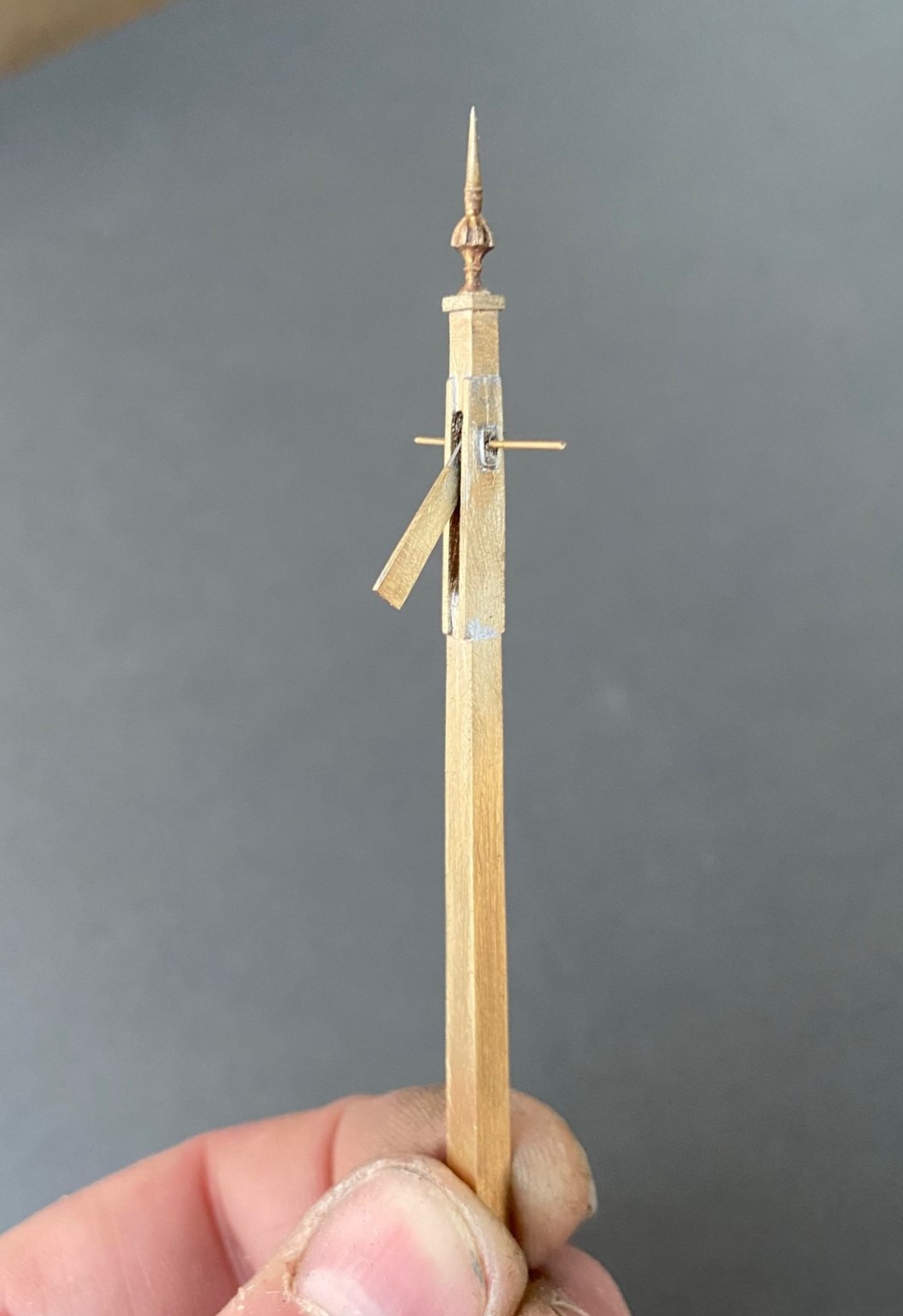
I had filed some 4mm square section into a taper to form the full length of the post. Even though I was about to cut a section of this out, it is necessary to form the full length of the taper so that it is consistent across its full length. Once I was happy with this, i filed two pairs of slots in the outside of the post on oppposing faces. The depth of these was such that the tongue between them was the correct size for the slot in the post. I chose to mount the finial at this stage, with some 296o solder and a lot of heat (from a minature blow torch). This is what it then looked like:
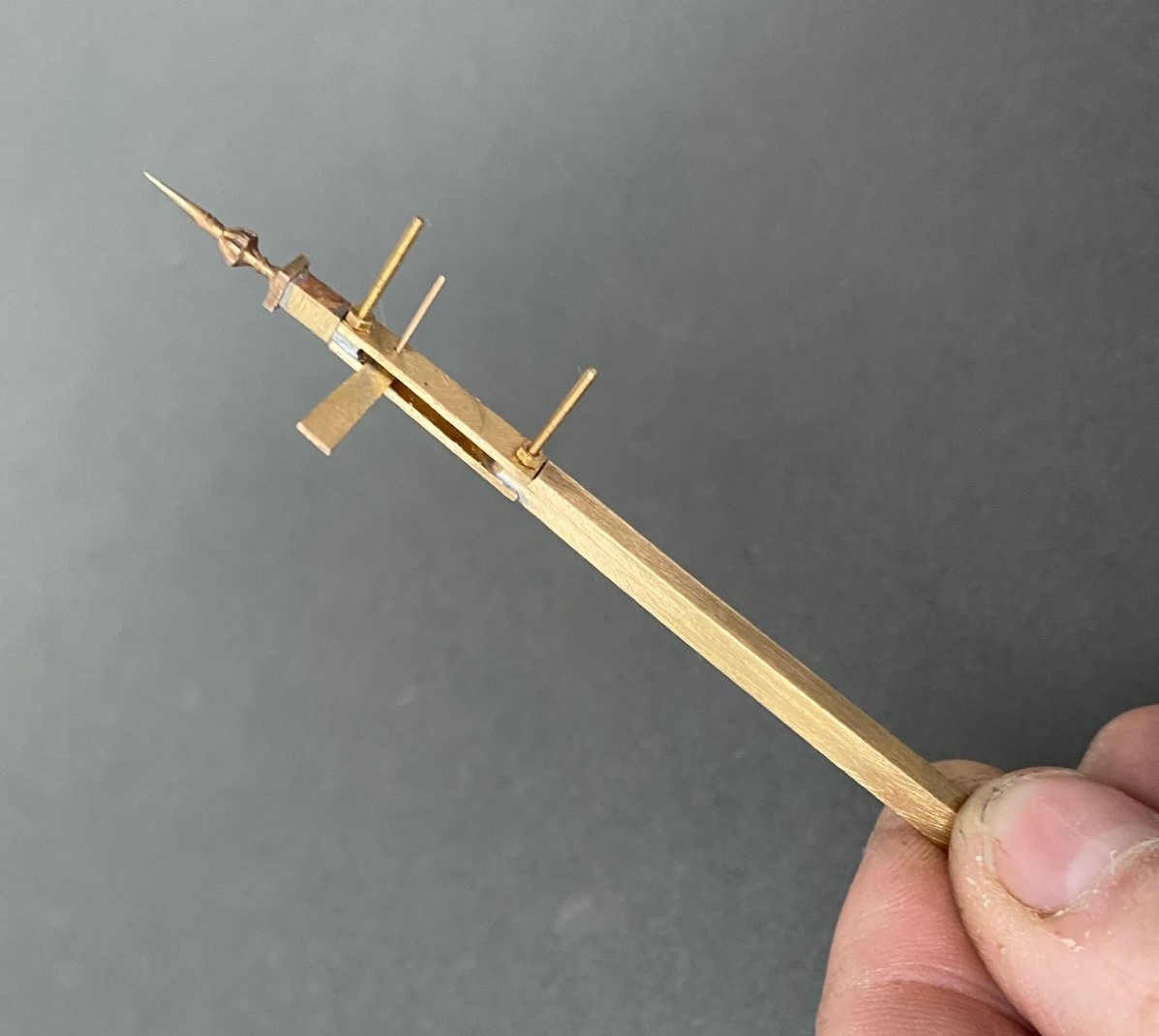
Next, I cut away the block of post that sits between the two filed sections to create a hole in my post. As there is around 2 hours of work to get the post to this point, it is a bit nerve racking chopping it like this! I then cut a pair of 1*4mm brass plate lengths to sit on the tongues and drilled both to receive a 14BA bolt. This was threaded through the first of the plates and adjusted until this a continuation of the taper of the post – this entails some filing of the metal to make the outside face match the post and plate match. It was then soldered in place, again using the 296o solder and a blow torch, to look like this:

The photograph above shows that these plates were wider than the post, in practice the prototype acheived this by planting timbers across these sections but it is easier to do this by way of using the sider plate material.
Temporarily mounting the second plate enables the hole for the arm spindle to be formed through both parts of the arm. The arm was now attached to the spindle with more use of the 296o solder and the use of a couple of minature washers either side of the arm so that I could be confident that the joint would hold.
Releasing the second plate now allows the arm/spindle assembly to be inserted and any adjustments made to ensure that it can move freely in the slot by securing the second plate in place with a 14 BA nut. The nuts and bolts are scarificed in the build by leaving them in place for the next step because once I was happy that it was correct I soldered the second plate in place including the nuts and bolts. This time I used 145o solder which meant that it would not disturb the first plate as I was doing this and this is what it then looks like – a slotted post with an arm within that is firmly attached to its spindle!
More to follow; including the second piece of bartering that I know someone is looking out for progress on!

Delayed Delivery – part 1
After a long pause, caused by that irratating thing called life getting in the way, I am looking to deliver on some long made modelling promises over the holiday season.
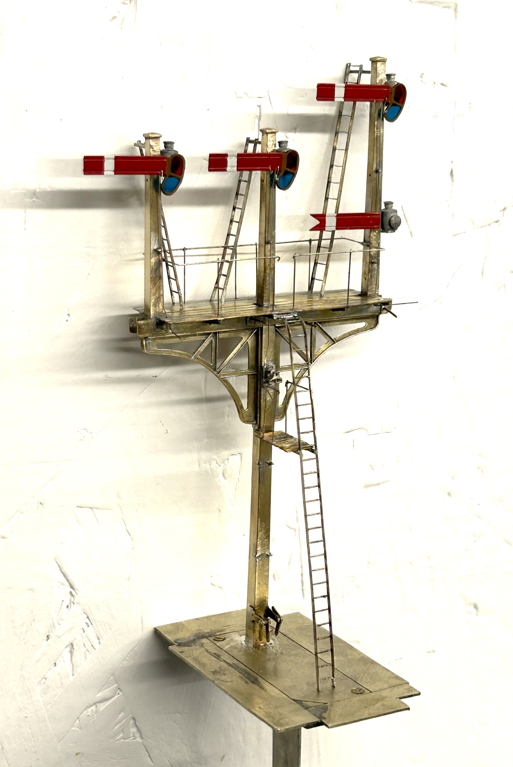
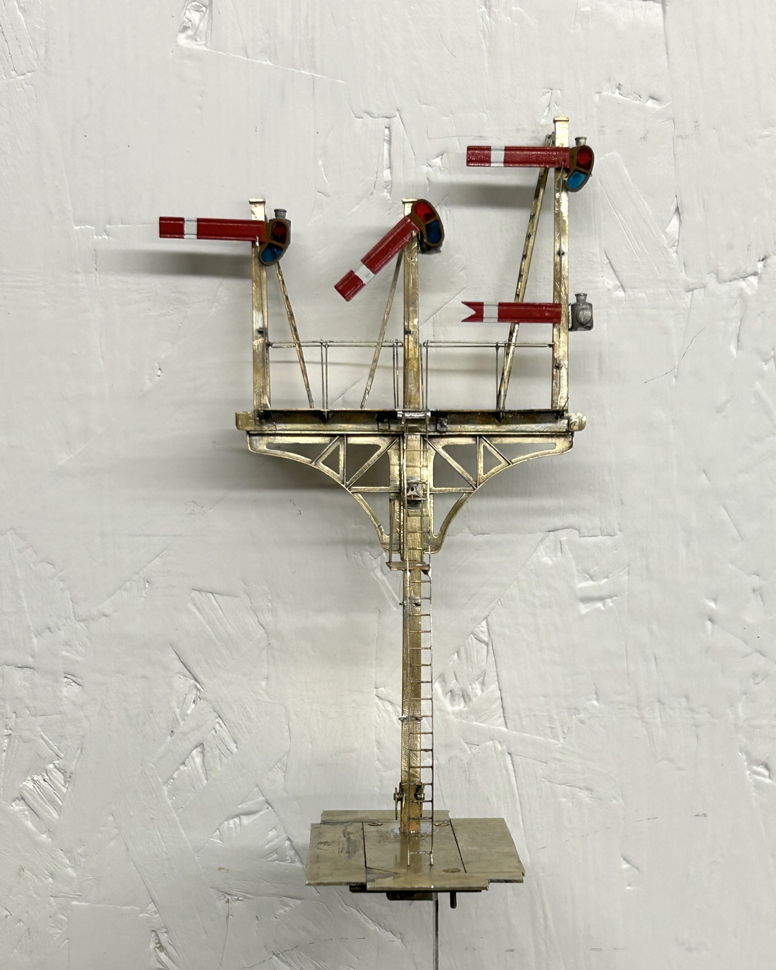
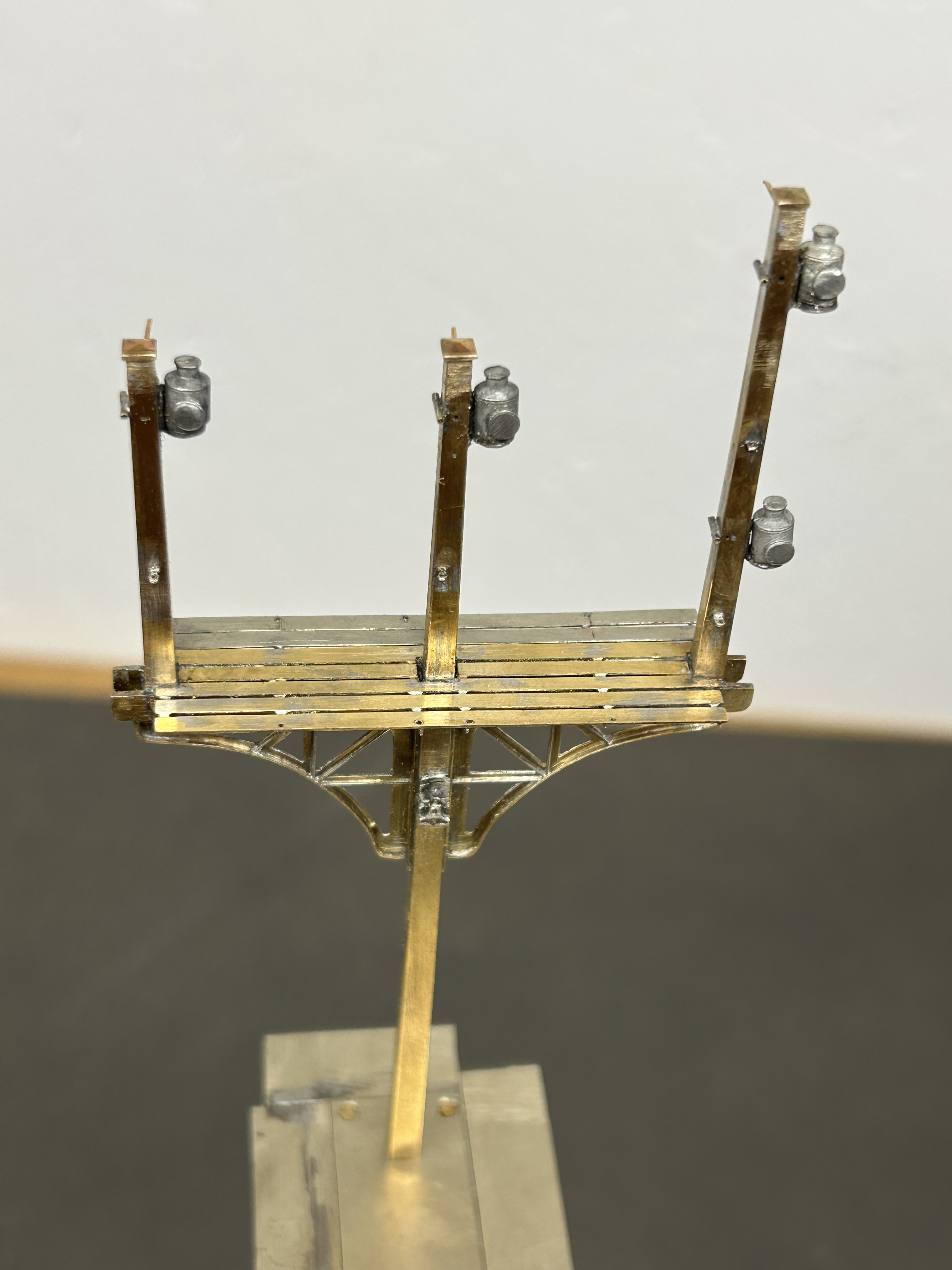
The major task is a rather full on gantry signal with no less than eight movements on it (which is an improvement, when initially designed it had nine!), including a rather natty fan route indicator. This is for a friend’s layout and is in return for some signal cabins that he built no less than 15 years ago – I told you the promises were long made! Mind you, he hasn’t got the layout fully running yet, so I am still ahead of him!
The gantry spans only two lines so it can be formed with channel section. There are good drawings and pictures in LMS Journal no 5 of this. I have made mine from milled brass section and then the landing was a custom etch I designed as it takes a surprisingly large amount of material and effort to construct this from scratch. These etches included the doll base plates although the dolls have a thickened tube at the lower level which of course I forgot and had to undo later work to put on!!
The signal is to be located on an embankment which meant that I could not simply put flat base plates on the foot of the gantry columns. Instead I have constructed a housing that matches the slope of the embankment and then the baseplates are partially sloped to match this with square sections representing the foundations of the prototype columns. Below these baseplates I have then formed housings to take the servos which will eventually operate the arm actions.
So far, this is pretty easy modelling (although I lost a number of drill bits opening up the stanchion positions on the landing – grrrrrr!). The tough bit comes next……………
There are potentially two viewers of this thread who might be thinking that I have long outstanding modelling promises to them too……………I am also working on one of these too!!
The Other Benfieldside
To date, the images and details I have shown on Benfieldside have related to the main and original station. However, there is more!
Benfieldside’s original builder, John Wright, constructed a significant extension a few years after completing the core layout. This was shown at the time in the Model Railway Journal (issue 57, 1992) and has not really be seen since.
When John’s interests moved on, he disposed of both parts of the layout and in turn the new owner decided he did not wish to retain the whole. However, he elected to retain the extension in order to convert it to P4 as his home layout (Benfieldside was all constructed as an EM layout). We all know what life is like – jobs, family life and other priorities get in the way but progress is now being made. The two main lines are now operational, as these two videos show.
The new layout will be NER as a core, but with also a Midland presence. It appears that the Midland has provided the motive power for the test train!
As you can see, Benfieldside’s extension was centred around a substantial viaduct with a degree of siding to one end. Its owner is proposing to make a small MPD here, the beginnings of which are visible in the videos.
There is still a way to go both in the adjustments around the MPD but also in refreshing the scenery. But never the less, as you can see it is another impressive layout.
The Other Auto-coach
Some time back I posted about the construction of a NER autocoach that I was building for Benfieldside and subsequently what it looked like once painted by Warren Heywood.
The NER generally used these in pairs, with a loco sandwiched between, although they did go out singly and even as quads. In this case, the Benfieldside team wish to operate them as a pair, as the bay to the right of the layout is conceived to receive such a train, with a NER / LNER G6 in between. This means that there was pressure to build the second from the moment I handed the first over. They have recently given me a favour, so it was high time I repaid it.
It is now completed down to the final check over stage (which has indicated that I need to put the steam heating pipes on – doh!) and then it can be delivered. So I have braved the fading light this afternoon (so sorry about some of the depth of field issues) to take a few pictures and to prove to the fellas it is done!

I completed a few personal upgrades to the kit in both this and the earlier autocoach. Chief of these is around the roof where I ditched the plastic roof and replaced it with rolled brass. This was formed of 0.25mm to give it a tangible depth, which makes its rolling a fair challenge. Add to this, I elected to cut out the portion below the clerestory, so that it was a clerestory! By the time I had added the gas lines and the various gas lamps and ventilators, I reckon there is around 20 hours in making the roof alone!
The prototype coaches were fairly long lived and numerous. They thus collected a good number of alterations and differences over time. I took some guidance to David Addyman and tweaked the kit in respect of gas lines, foot steps, handrails, footboards and gas cylinders. If someone thinks this is wrong, please don’t tell me!!
It always amuses me that the driver had to stand and peer down the line through two tiny windows. They lived in different times – could you imagine the snow-flakes tolerating this in the 21st century?
These are rather beautiful coaches, but not for the feint-hearted as there is a lot of time invested in these. I am pleased I do not have to paint it!

Back from the Paintshop
Some while ago, I showed a completed NER auto-trailer and mentioned that it was for the paintshop. Given that it was to go into full NER coaching livery I am pleased it was not my paintshop!
Well, it is now back and doesn’t it look fine…………..
The painting and lining has been done by Warren Haywood and as you can see there is little to fault about it. It now needs finishing with grab handles, buffer heads and glazing.
And that reminds me that I have another one in the box and they did tend to operate as pairs……….
Only the printable words for this Wednesday!
Hmmmm……..
A signal imitating a Fresian cow was not the effect I was after…………..
Halfords etch primer is obviously not that etchy!…………….. So someone will be waiting a tad longer for their signal than I thought…………
