Blog Archives
More Weathering Results
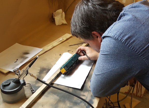
The class 24 skinhead was not the only output from the weathering day last weekend – indeed, it was a very busy day!
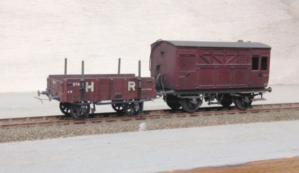
First up were some of my 1920’s rilling stock – both Highland, a timber truck from a Model Wagon Co whitemetal kit and a horsebox from a Lochgorm etched kit. Both are now close to finished – a load is requird for the former and some glass for the latter (and probably a light colour inside the groom’s compartment.
Neat vehicles though and I am pleased with them – less so than the brakevans that I managed to dislodge the lettering upon and may well need to be stripped – as you would imagine, no photos of these and nor any photo’s from today’s efforts with paintstripper!
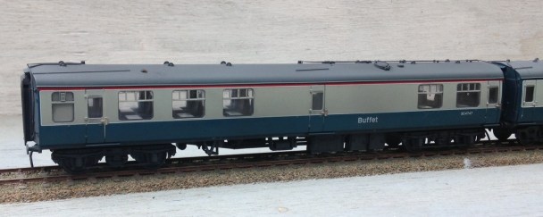
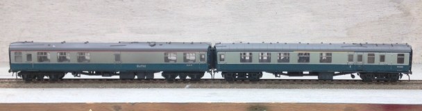
But the main additional output was some more coaches for Portchullin. I managed three and Peter Bond looked close to finishing his third as I left, so we had a proper little production line going!
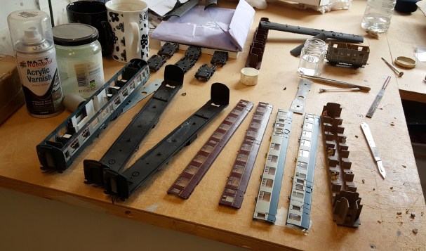
The technique was essentially the same as I described for the class 24, although as you can see the model was broken down rather more (in part to populate the interior of the carriages – I do hate seeing trainloads of empty coaches on model railways!). However, for the maroon coach, rather than using thinners to take back off the paint, T-Cut was used. This is an abrasive so does not work in quite the same manner but acheives broadly the same effect except that it also polishes the paint. I did not think this was right for the blue/grey coaches (they were finished in satin in reality) but the maroon coaches were in a gloss finish and the T-cut gives a slight sheen without actually getting to gloss. I did eventually think it was a bit too shiny, so did waft over with the finest of sprays of the “gunk” again just to take it back a touch.
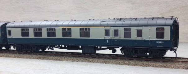
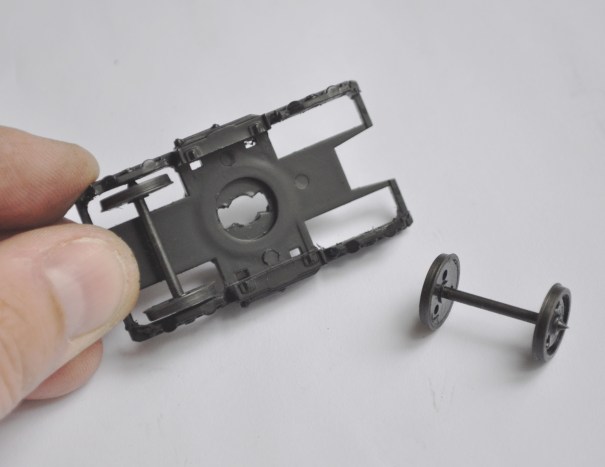
The Bachmann Mk 1s are very good models that have stood the test of time well. They are a doddle to convert to P4; taking maybe 60-80 minutes a go. There are a couple of things to look out for – firstly is that the side frames are a touch to tight for true guage wheels and need to be filed back. The plastic is quite flexible and does create burrs fairly easily, so once the filing has been done some work with a sharp scalpel is required to clean this up.
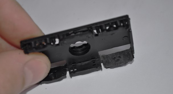
The next caution is that the bogie mounts are not always parallel with the rail head, meaning that the bogie can lean forward or backward. This is caused by the chassis being screwd a little over-hard onto the body, causing it to flex slightly. You are just as likely to have done this as the manufacturers and I get around it by making it rock slightly with some thin (20 thou) strip like this.
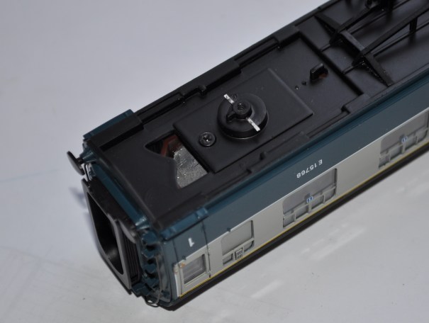
Arguably one of their weaknesses is the corridor connection which is a tad toy-train (well it is a toy train!). A dodge that I have started to do is fit a few of my vehicles with some black foam in the door jambs. Make this so that it sticks out 3-4mm and engages in the equivilent of the adjacent vehicle to block out the light. A simple dodge that makes a big difference. It does mean that the vehicles that are fitted thus have to be in the centre of the train (as the foam looks crude where it is exposed) but this can be done with care – for example a buffet would nearly always be in the centre of a train, so this is the vehicle of the two I fitted with this.

New Shoes for Some Old Friends
Over the last few weeks, I have been revisiting a number of model coaches that I have built in the past, typically quite some time in the past as most of these have been around since either my teens or twentys!
Over the years techniques have changed and I undoubtedly would not build most of them in the manner that I originally built them if I was confronted with doing them again. Having said this, on the whole my handiwork – especially in respect of the painting and lining was really quite good. I seem to have lost my lining mojo in particular, so I am not sure I could line as well as this now. This is something that I really must get to grips with this, as I still have a lot to do!
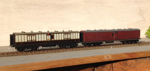
a pair of full brakes, the one to the left is a West Coast Joint Stock (from a London Road Models kit) and that to the right is straight LNWR (from a Microrail kit)
But the biggest area of difficulty with the coaches is that the bogies were generally formed around beam compensation units. These are OK for a couple of coaches behind a branch train but they impart far too much friction for a full main-line train as I aspire too. This is impossible to overcome whilst retaining the compensation units, the bar is the cause of the problem and it has to go!
To overcome this, Bill Bedford sprung boiges are being retro-fitting to all of my existing stock. These rely on separate hornblocks that secure a pin-point bearing in them – so rolling resistance is significantly reduced. The hornblocks are held in place by way of guitar wire and the effect is that they glide around the trackwork. They thus give the impression of weight and inertia that is much better than compensation (it is possible to get compensation that does not use the rocking beams that are the cause of the fritchion I am complaining about).
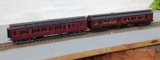
A Midland & North British luggage composite (from a PC Models kit) and a LMS (ex Midland) dining car (from a 5522 Models kit).
The Bill Bedford units are only an inner bogie and they still need to have some form of detailing on the outside. Some of these have entirely cosmetic outers, either of plastic or white metal but the two Midland coaches and the Highland TPO have something slightly different. On these, I utilised the original etched bogie sides and laminated them onto the Bill Bedford inners. This is very successful as it improves the Bill Bedfords notably by making them a lot stiffer and you get the crispness of the etching process.
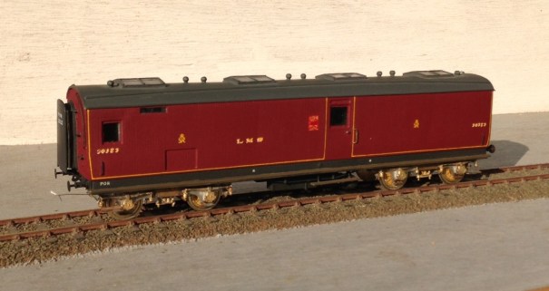
This is one of my fathers, so I can’t claim credit for anything but the bogies. A Highland Railway TP (fully scratchbuilt). Obviously, no painting has as yet been done, so it does rather look like a ganster with gold teeth!
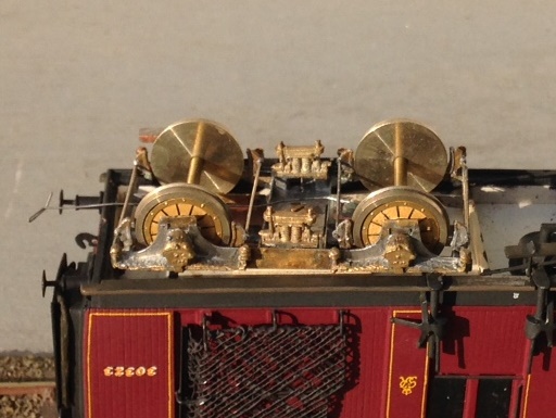
It is rather challenging to see how the Bed Bedford sprining unit sites inside the outer skins (from a Lochgorm kit) – so I will write up the process in a future blog – but this is what it looks like from the outside.
If, by the way you fancy some Fox Pressed Steel bogies that are neatly sprung and look the part – and almost all pre-group modellers ought to – keep watching the space. Subject to a test build or two, there will shortly be one available on the market.
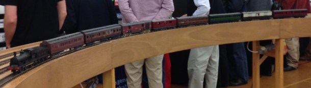
To test them, I took them and a few other coaches to ExpoEM to use their test track. Here we see a Barney with eight on – albeit a rather od mix for the train and there is a fair amount of painting and lining still to be done.
And to prove that they really do work and also to allow you to see how they glide, a quick youtube video: https://www.youtube.com/watch?v=6D7a_cWwGhg&feature=youtu.be

The Far North Line
In my last visit to the Highlands, I took my father up to almost the extremity or our island to Thurso. The purpose of doing so was to mooch around portions of the Highland Railway north of Dingwall but also to drop in on Richard Doake. Richard is a fellow follower of the Highland Railway and has a rather nice layout depicting a pair of the Far North line’s more interesting stations; Helmsdale and Thurso.
Although Richard has sought to use a large degree of ready to run stock, most of the infrastructure on his model has been scrachbuilt so that it captures the Highland flavour. This includes signal boxes, goods sheds, water tanks and the like – the combined effect works as this is one of the most authentic feeling Highland layouts I have seen.

An overall view of the main part of Thurso.

The train shed is a reduced liength version of the real thing (which is still there for those that don’t know). This view would have been a daily occurance in the late 1950s as a hiker concludes its long journey from Inverness with the Thurso portion of a Far North train.

The signal cabin at the station throat.

A small ben, Ben Wyvis, does some shunting in Thurso’s yard. This has been converted from a Hornby T9 with a replacement tender. The wheels are in reality 6 inchs to big and the boiler is consequently too high, but I bet the Highland fans that read this didn’t notice until I told you?

Brn Wyvis’ sister, Ben Clebrig acting as station pilot at Thurso.

The other station is Helmsdale and here we have the Hiker once again returning south. passing a typical Highland goods shed.


A Pickersgill on shed at Helmsdale, along with a pannier. A pair of panniers were regularly found at Helmsdale in 1962 as they worked the Dornoch branch at this time following the failure of the last operational Highland locomotives, some small tanks.

And here is an example of this tank – aptly named Passenger tanks as they specialised on lightly loaded trains on the short branchlines the Highland had a number of in their region.

Like on the Kyle line, van traffic was a big feature of the line and here we see a clan pull out northwards with a train of vans and non-passenger stock. The eagle eyed will notice that the clan is in BR livery where in reality they did not last long enough to carry this. Richard is quire relaxed about this as it enables him to include locos he fancies!

And a similar working heading south with the almost enivitable (for the real thing) black 5.
So thank you Richard for entertaining us and also for the use of your photographs – rather better than my own!
The Dingwall & Skye Railway
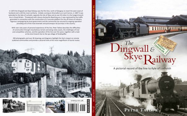
The Dingwall & Skye Railway – A Pictorial Record of the line to Kyle of Lochalsh.
For those of you that are aware of my main exhibition layout you will be aware that it is based very firmly on the Dingwall & Skye Railway, which is the name of the line we now call either the Kyle line or occassionally the line to Skye.
I have to confess that the layout is heavily influenced by my memories of family holidays to the line in the early 1970s – we were dragged up there by my father and I at least (it all appears to be lost on my brother!) picked up a bug for the railways west of Inverness. This bug seemed to have been passed to me by my father and he was in turn infected in the late 1950s when he first made his visits to the area.
Based on his love of the line to Kyle of Lochalsh, my father’s latest book is upon the line. It does not seek to be a strict history of the line (Rails to Kyle of Lochalsh does this) but is instead a review of the line on a station by station basis. It is full of photographs (literally hundreds of them) and also a substantial number of drawings of the engineering and architectural infrastructure apparent on the line as well as around it. This covers station buildings, water tanks, bridges, sheds, signals, water columns, water tanks, cattle docks and indeed many other aspects of the line. There are historical reviews of aspects of the operation of the line, the exploration of alternative schemes that did not come to pass and some of the quirky storys of the past.
It is thus for those that like a coffee table picture book, a historical review of the highland railway, those that are interesting in modelling tbe line and those that simply are caught up in the nostalgia of the “line to Skye”…..
The Dingwall & Skye Railway – a pictorial record of the line to Kyle of Lochalsh, by Peter Tatlow ISBN 978 1906 537463 @ £27.95 by Crecy Publishing Ltd. For those of you who are members of the Highland Railway Society, you will find that your membership entitles you to a significant discount if you buy from the society. Thus if you are waivering about joining the society, you will be do well to do so if only to buy this book!
A Quiet Day at Portchullin…………
Although it may be that there is a train in the yard as the shunt signal is off…… I suspect it will be one of the class 24s?
Portchullin is just back from a trip to the St Alban’s show and its next outing will be in Telford, for the Diesel & Electric Show on the 20-21 February.
With thanks to David Brandredth and Tim Venton for the cracking photo. Now my fav of the layout!
Glenmutckin Shed Area
Glenmutchkin’s shed area is modelled on Kyle of Lochalsh’s (it is a mirror image) and I wanted to capture the typically cramped feel of the inspiration. This is the original OS map for the shed (ie old enough to be outside of copyright).
Key to this is the way that the whole complex centres around the turntable and the first turnout is almost tight against the turntable’s wall as this photo extract shows (notice there is not even a buffer stop on the far side of the well):
The first turnout is, you will see, a tandom and whilst it is not visible in this picture, almost certainly it was interlaced (as the Highland always seemed to always use interlaced turnouts). Well, interlacing gets quite crowded on a tandom turnout, as you can see:
It takes a long time to do all of the sleepers as there are a lot of them but once it is done, it does look rather impressive don’t you think?
_________________
Mark Tatlow
Testing Times with Terribly Troublesome Turntables
A decade or so ago, I did start a MPD type layout and got some way with the building of a working turntable but had lots of trouble with it and this did rather kill off my enthusiasm for the layout – with inevitable consequences…………
The difficulty was to get it to operate smoothly, with any level of reliability, and to stop with sufficient accuracy to enable P4 wheelsets to enter and leave the turntable without derailment. Well, Glenmutchkin needs a turntable, so it is time to confront that particular demon again – and he has not gone away in the meantime! However, I think I have put the blighter back in his box with the help of the Chatham Turntable Drive, a chunk of scratchbuilding and a dose more cussing………..
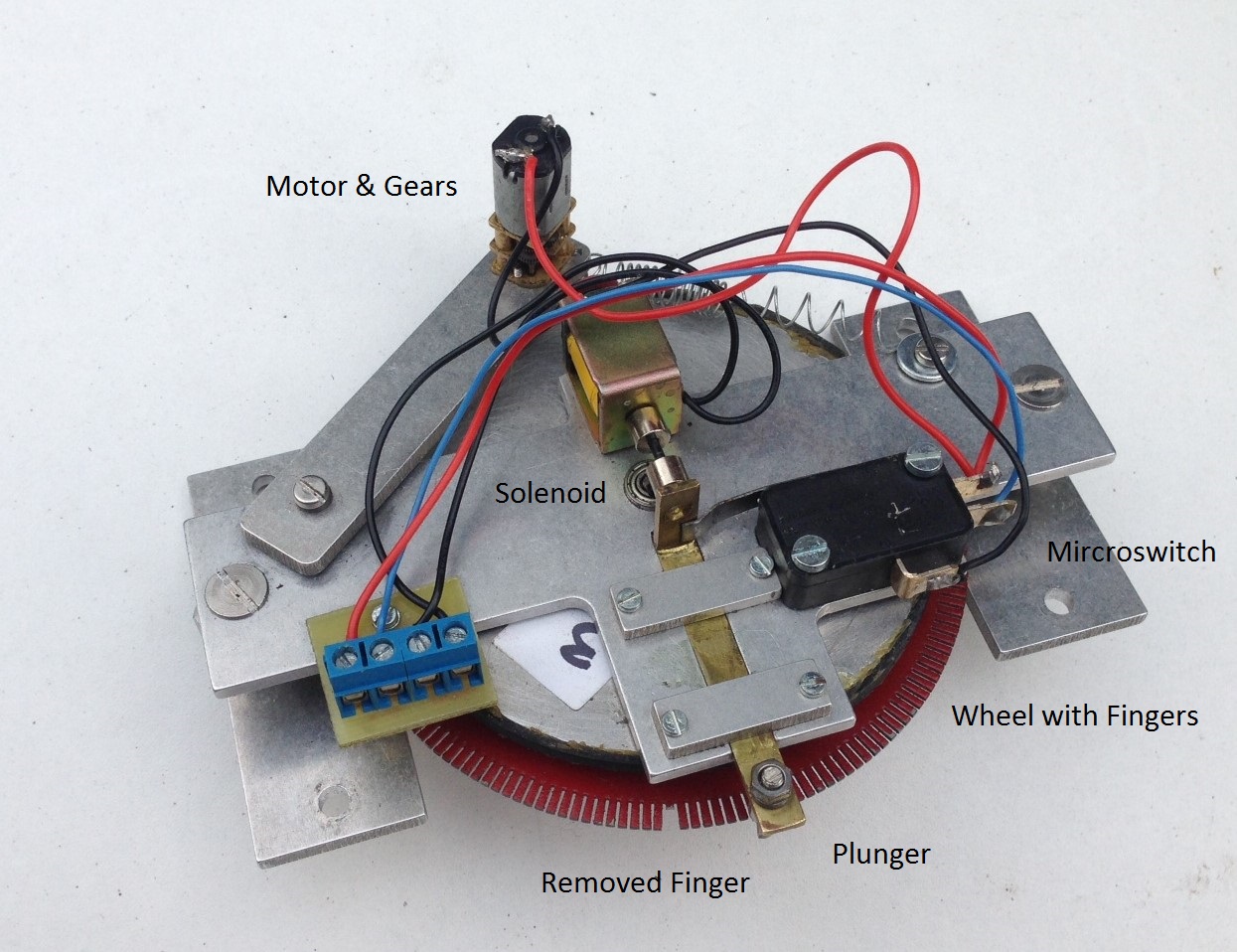
The Chatham turntable drive is named after its originator and is supplied in the UK by Model Railway Developments – not a great site listing I know, but there is a better Youtube video. The attraction of this particular drive was the mechanical locking arrangement – this means that it both stops consistently and then holds the turntable deck firmly there until activated again. The basis of the drive is a large wheel that has numerous fingers cut into it – the user then takes a finger away for the positions at which it is desired that the turntable will stop. When operated, a plunger runs across the tips of the fingers but where it encounters a gap, the plunger is pulled into the gap and cuts the power at the same time. To operate it again, the plunger is pushed free of the gap by way of a solenoid and the power to the drive reactivated.
The concept is great but there are some issues. The first was that the solenoid did not fully operate when activated. I found two problems with this; the first being that the control box seemed to send a less than full voltage to it. This was fairly easily dealt with by bypassing the control panel with the push button. The second problem related to the microswitch that alternates the power between the solenoid and the drive motor. The spring to this, even though it is quite light, was sufficent to offer to much resistance for the solenoid to overcome. I managed to overcome this by making sure that the rest of the plunger is as smooth as possible by rubbing all the parts down with fine wet and dry and a touch of oil. This takes a degree of care to set up to get the balance right and I am worried that it will be a source of problems for the future but for now it works.
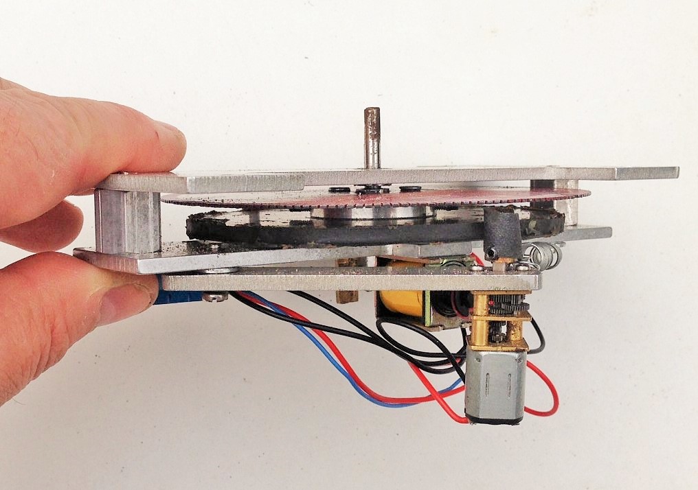
The next issue, is that the motor is not engaged to the drive wheel by a mechanical set of gears and instead has a brass wheel that runs on a rubber rim. This is probably designed as a safety feature to stop the motor burning out when a problem is encountered but it is prone to slipping rather too much. I have sought to overcome this by way of wrapping the motor wheel with sandpaper but this has only been partially successful. There are still more tweeks to do but I have found that it works rather better in one direction than the other, so this may be the ultimate solution!
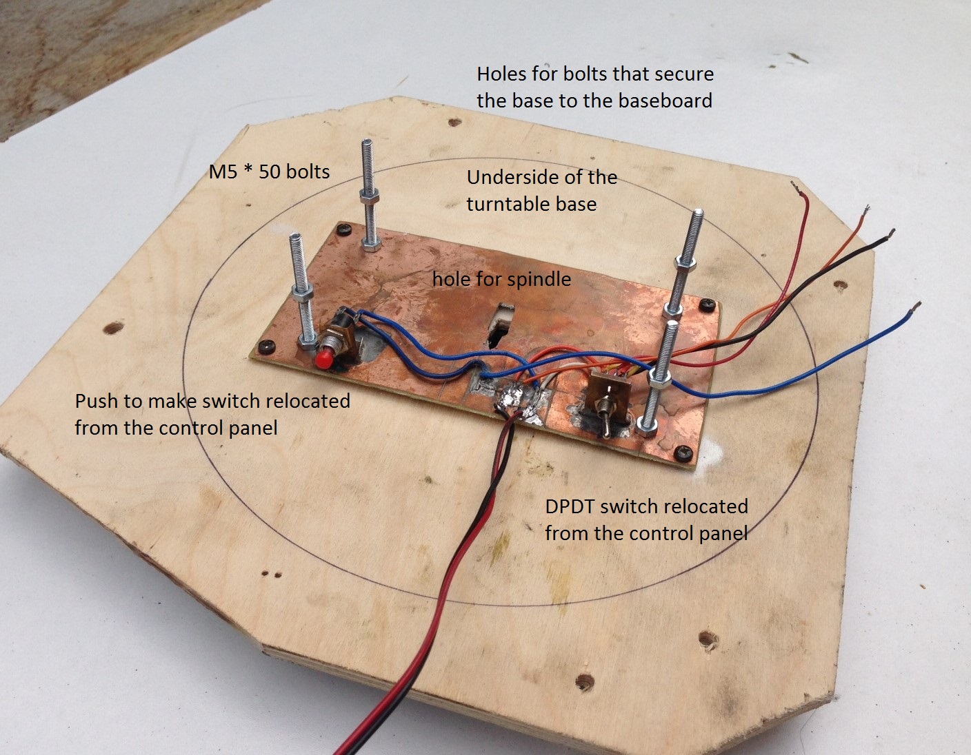
The next issue was to set the ride height of the turntable deck up correctly. I found that this had two aspects to worry about; the height of the deck relative to the rails that it runs on and then the height of the deck relative to the approach trackwork. I found that it is not sufficient to simply seek to try and get the deck set up correctly with fixed construction – it was simply too sensitive to minor errors. Therefore, I made up a mount with 50mm M4 bolts. By threading on a pair of nuts onto this, it was possible to adjust the exact positioning of the drive relative to the deck and then the entire assembly with the baseboard. The first of these nuts is shown on the above picture and once the drive unit is in place. the second set is tightened from above to hold it all in place. I am concerned, however, that they will loosen over time – so some “nut-tight” has been added to the shopping list!

I connected the shaft of the drive unit onto the turntable deck by way of a small piece of tube. This had grub screw clamps onto the drive unit shaft and a permenantly attached bolt on the top (bottom in the picture). The rod to the base of the turntable deck was reduced in diameter slightly such that it would rock just a touch and take up any inconsistancies in the turntable well. However, I ensured that the bolt was tight in both the rod and tube, so there was limited backlash.

Next up was a turntable well; which was another area where the gremlin made itself felt last time. Most of this had to do with trying to get the turntable deck to sit squarely and equally in the well. As already noted, I adopted the oppisite approach this time and built the well to fit the deck and simply relaid the rail afterwards so that it was exactly above the pivot – it has proved to be a whole lot easier and could have saved a lot of frustration last time!
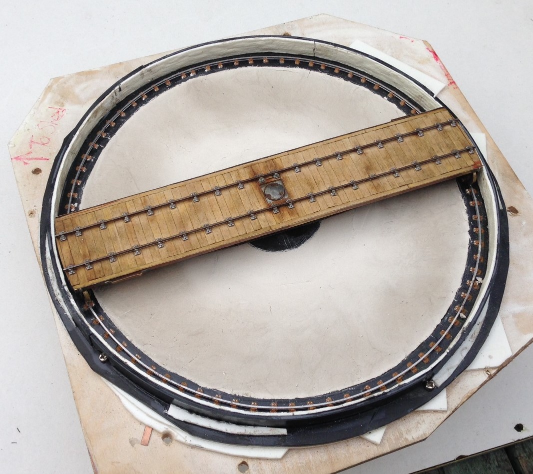
The well walls were formed of Will random stone sheet, as I did not think that they would have used anything particularly fancy on a turntable well. However, to stop them springing out of the curve, I laminated this with a chunky thickness of plasticard and also secured them to a plasticard base – this also formed the base for the rail, which is secured in turn with Exactoscale chairs. One thing I did notice when studying prototype photos is that the chairs on the turntable rail are quite closely spaced – presumably because a relatively limited number have to support the entire load of the engine (much less in number than in plain track due to the deck carrying the entire weight of the loco onto only four points). I have replicated this on my deck.
The dish to the well was, I have decided, merely ash ballast in the pre-group era (neat concrete was a much more recent approach), so I formed this with Das pressed into place and made as smoth as I could make it with fingers. This never gets crips and “machine made” so represents what I think it will have looked like.
I will look at the deck in the next post, after which hopefully it can be shown fully working and in situ! However, here is a peek:

….alliteration with thanks to Mrs Bennett; I really do remember Magistrate Maskew of Moonfleet Manor……..!
Scrap Tank Test Build Part 9 – Finishing the Body
I have now had the castings back for the various fittings for the Scrap Tank; the masters being in part my own 3D prints and some turnings that I commissioned from Jeremy Souter. This is what they look like:
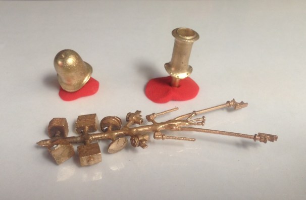
I did not seek to do everything for the whole model as some parts are available from other suppliers and I did not want to duplicate their work. Thus, I needed to get the safety valve/safety valve bonnet from Alan Gibson, a smokebox door from Lochgorm, a whistle from Markits and smokebox door handles from Comet.
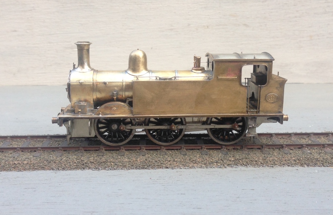
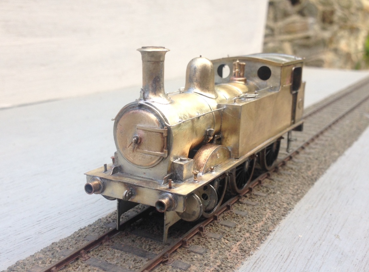
Once these, along with the remaining handrails, were fitted, the body is complete and it certainly appears to be taking on the character of the real thing so far as I am concerned!
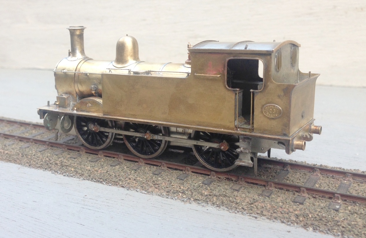
So next up will be the cylinders, crosshead and connecting rods!

Aultbea Revisit
A year ago, I posted a few photographs of one of my friend’s layouts, Aultbea.
Peter has been making progress with the layout and now has the bulk of the trackwork laid, so it is worth having another look at it:
As you can see, it is a bit of a beast because this is only the passenger station complex, the MPD and sidings for the military are not even on show here!
The full extent of the layout can be seen in the previous posting and you will see he that even the bay is conceived for a seven coach train. Looks like Peter will need to be building/converting and otherwise acquiring a fair amount of stock!
in the views you will see that a some of the buildings have been finished – the signal cabin and the water tower. I think station buildings are next and before too long, he will mention signals I suspect!
One for the Gorilla – tracklaying progress
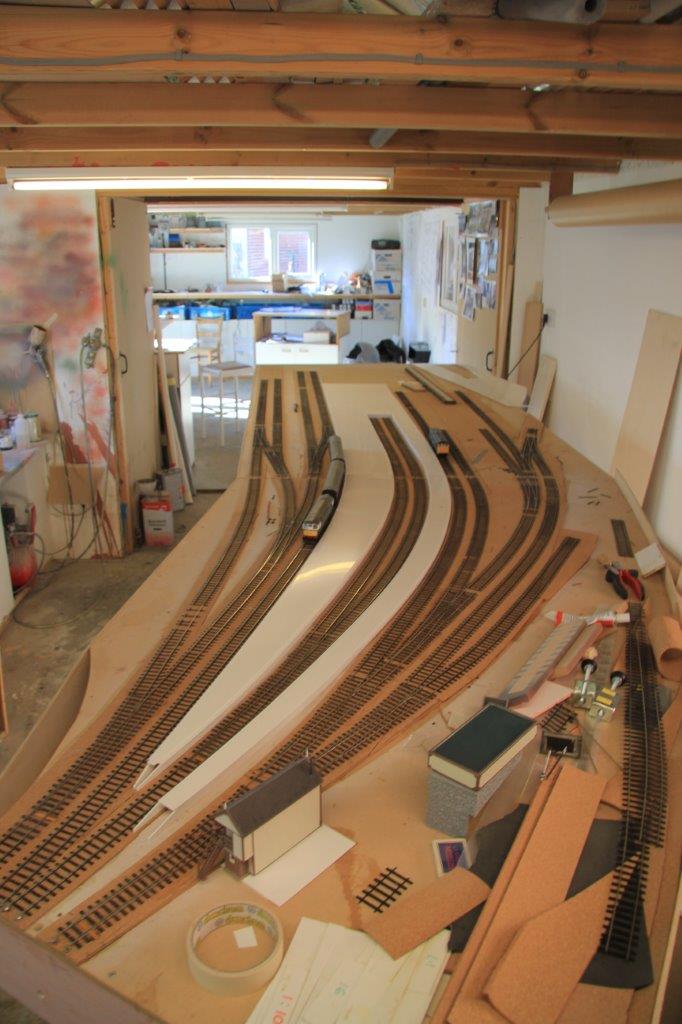
Matters have been progressing with the layout on and off through the summer and a lot more of the track has now been laid. We have both the main line and the full run around loop complete, along with most of the bay and its run around loop too.
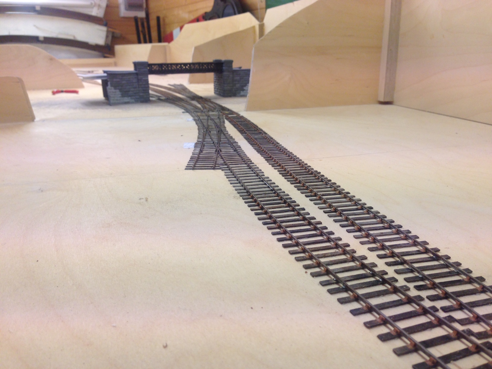
The line diverging in the foreground is going into the shed area, those visible below the bridge go to the bay (left) and yard (right). A signalling trackplan can be found here.
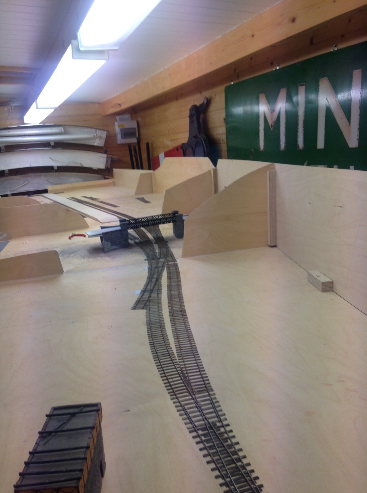
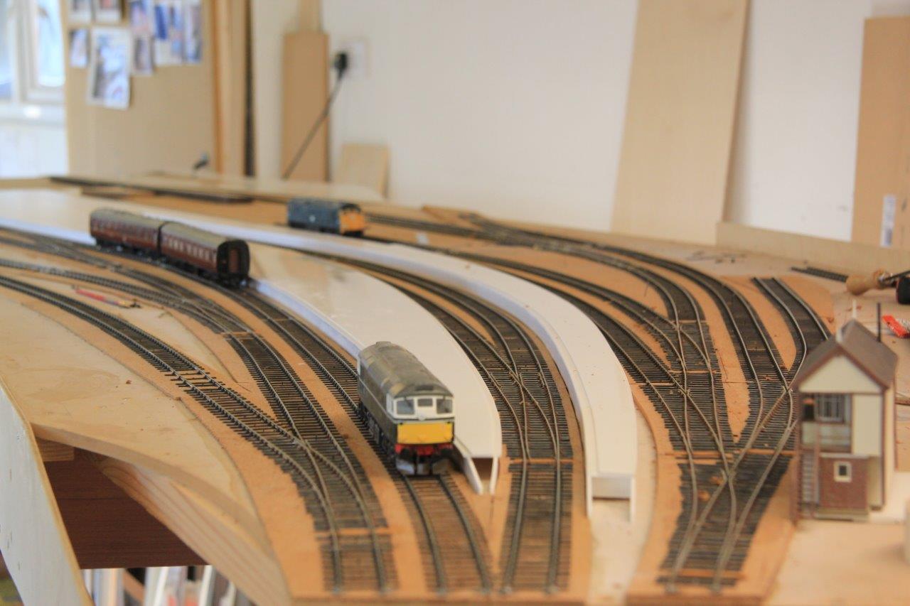
I quite like the sinuousness of the line, which can be seen here/ I have done this in order to give interest to the layoput but it is pretty typical (indeed characteristic) of the lines to the west coast as they wind through the mountainside. I do have in mind some hills to justify this in the finished item.
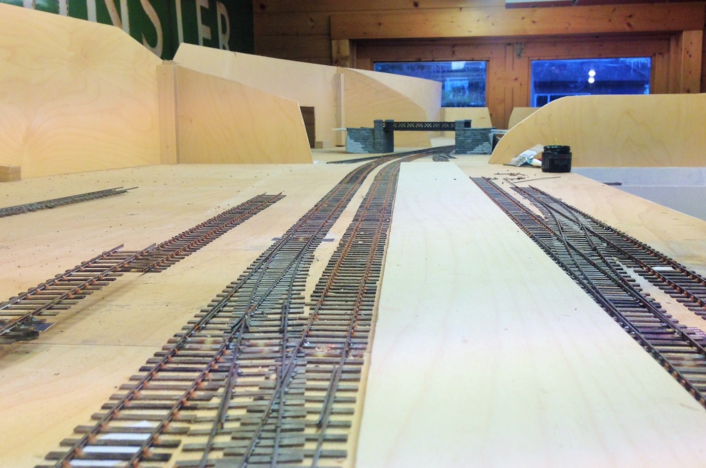
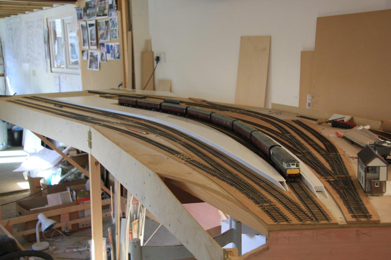
Already there is a sense of magnitude to the station forming, the platform face (which is not all in view in either of these views, comes in at about 7 feet – enough for an eight coach train of pre-grouping coaching stock. Really, its length is defined by the length of the bay – this will become clearer when the train shed appears because the bay has to start clear of this..
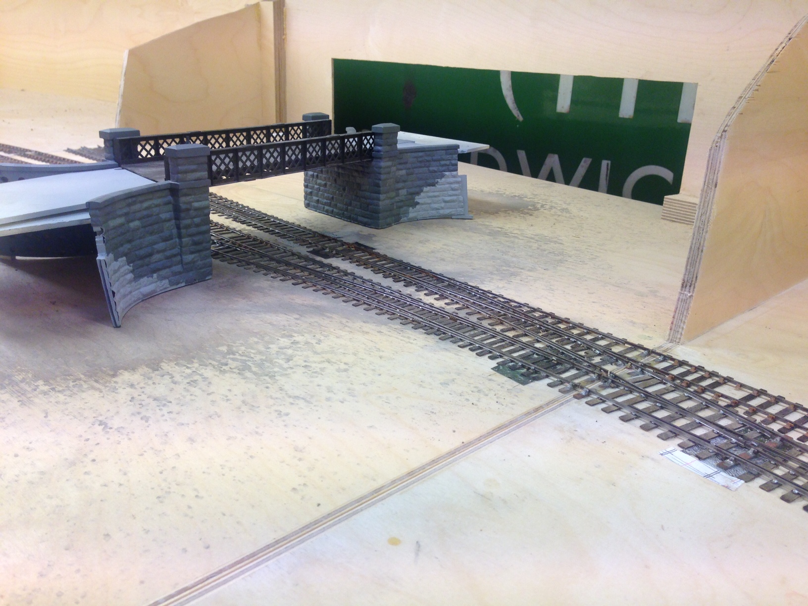
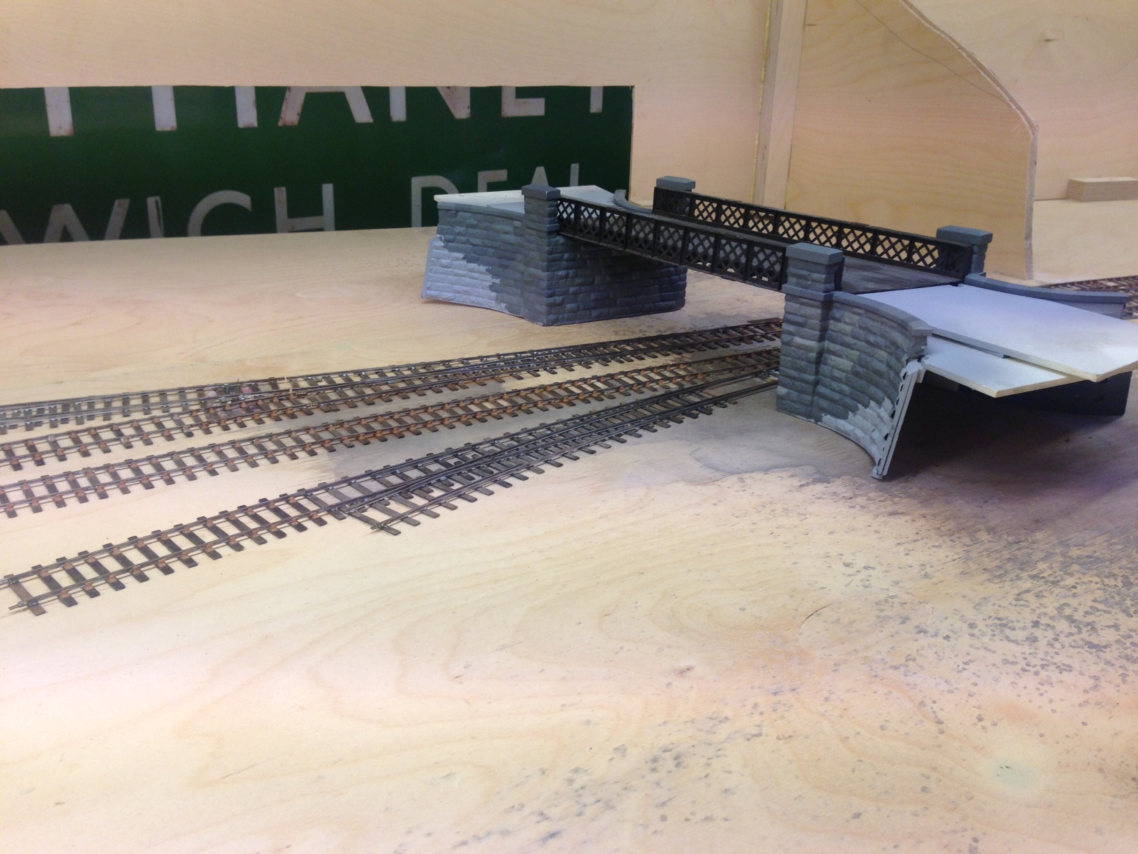
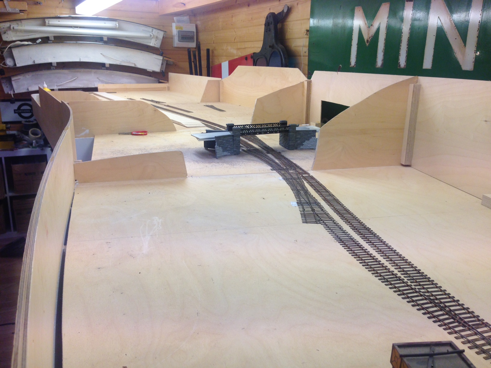
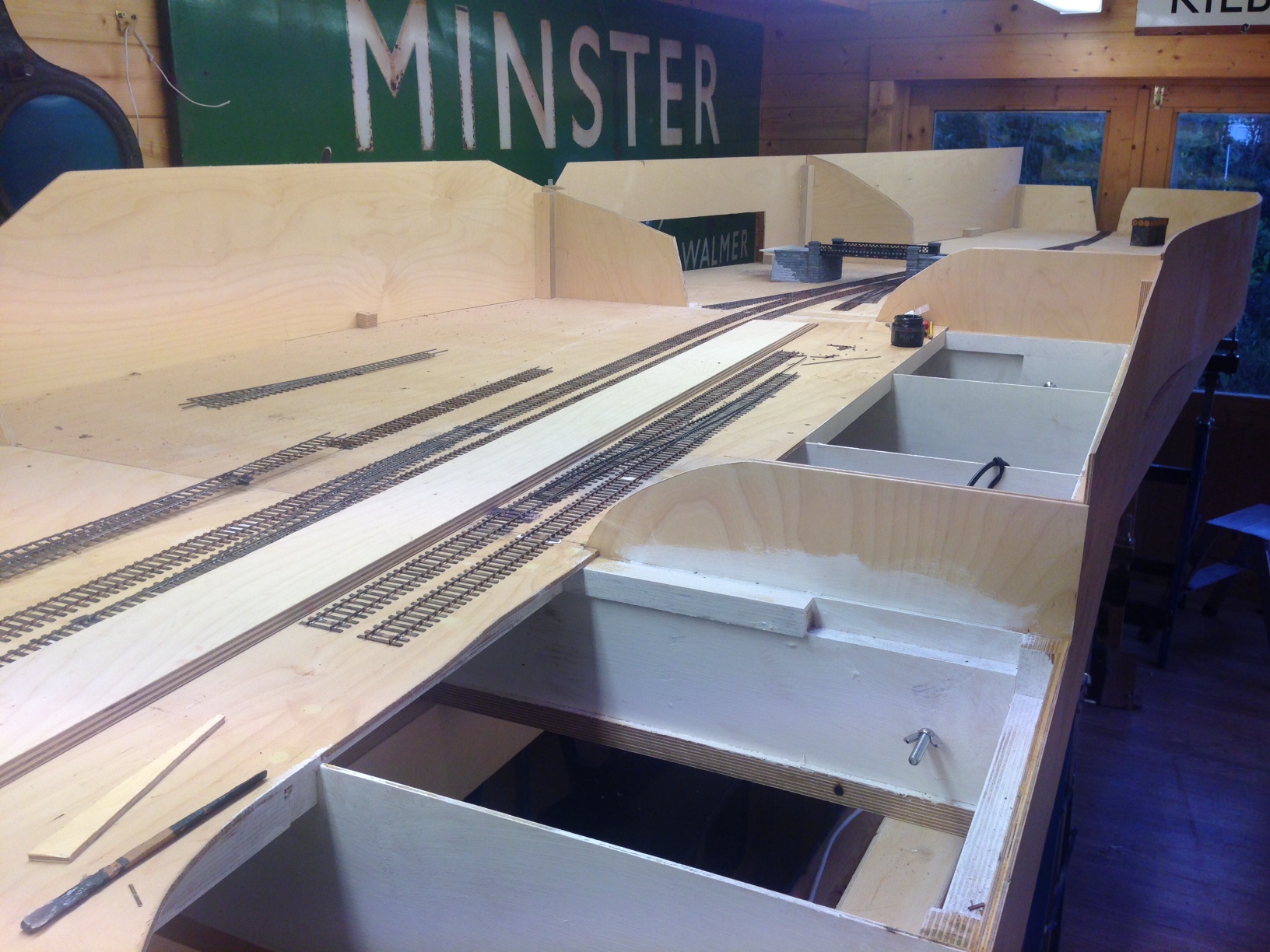
I have also placed into its approximate position the road overbridge that separates the shed from the main station area. The construction of this can be seen in postings here and here. The intention of hte bridge is to act as a scene blocker and thus to compel the watcher to view the layout from more than one location to appreciate it.
