Blog Archives

Delayed Delivery – Part 2
Once the basic structure of the gantry is in place, the real task of making the signals signally commences. First up were the smoke deflectors and the brackets for the balance weights. Also fitted are the main portions of the fan route indicator, but that will be explained further once I get it going!
For the arm bearing point and lamps I am using some 3D prints produced by Steve Hewitt and available from Shapeways. They can be found here https://www.shapeways.com/product/JJRSB … arketplace. They are fairly expensive but they are neat and save a lot of manufacture. There is, however, a but – they are very delicate and I am very fearful of thier long term durability. I am highly likely to draw some of my own up and get them cast in lost wax. It will make them even more expensive but I have about a 50% casualty rate at the moment, so maybe in the long term it will be cheaper!
The arms are Masokits, these are definitely the best available arms for LMS/LNER/BR semaphores. This is especially true of the minature shunt arms as the MSE ones are simply too delicate to bother with (imagine how do I know that………….!). So this is where we are now at with the arms mounted temporarly on the bearings.
There are five movements in the down direction (three of which operate via the route indicator) and then a pair in the up direction – hence the back to front arms.
The plates at the top of the dolls are mounting points for ladders. It transpires they are wrong and have already gone!
So the intensity level has dialled up a notch with these portions (especially breaking the bearing/lamp fittings) but it really gets interesting when you try and make these things work.
I don’t know myself yet (although I know for the couple of arms I have finished, so I have an inkling), but i think it might be fun to have a little sweepstake on how many moving parts there will be in the finished gantry. Five arms, three fan route indicators and each is operated by way of angle cranks. Each arm, crank and intermediate wire counts as a moving part, as do the servos………………..guesses please?

Delayed Delivery – part 1
After a long pause, caused by that irratating thing called life getting in the way, I am looking to deliver on some long made modelling promises over the holiday season.
The major task is a rather full on gantry signal with no less than eight movements on it (which is an improvement, when initially designed it had nine!), including a rather natty fan route indicator. This is for a friend’s layout and is in return for some signal cabins that he built no less than 15 years ago – I told you the promises were long made! Mind you, he hasn’t got the layout fully running yet, so I am still ahead of him!
The gantry spans only two lines so it can be formed with channel section. There are good drawings and pictures in LMS Journal no 5 of this. I have made mine from milled brass section and then the landing was a custom etch I designed as it takes a surprisingly large amount of material and effort to construct this from scratch. These etches included the doll base plates although the dolls have a thickened tube at the lower level which of course I forgot and had to undo later work to put on!!
The signal is to be located on an embankment which meant that I could not simply put flat base plates on the foot of the gantry columns. Instead I have constructed a housing that matches the slope of the embankment and then the baseplates are partially sloped to match this with square sections representing the foundations of the prototype columns. Below these baseplates I have then formed housings to take the servos which will eventually operate the arm actions.
So far, this is pretty easy modelling (although I lost a number of drill bits opening up the stanchion positions on the landing – grrrrrr!). The tough bit comes next……………
There are potentially two viewers of this thread who might be thinking that I have long outstanding modelling promises to them too……………I am also working on one of these too!!

News from Miscellany Models
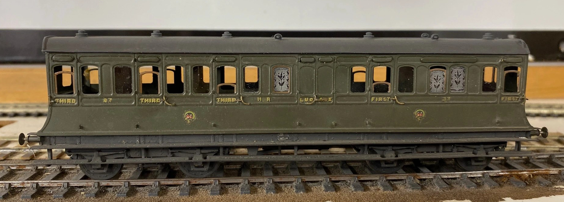
With the assistance of Duncan Petford, Miscellany Models are now offering engraved glass windows featuring the thistle emblem that the Highland used to obscure the windows of toilet compartments. They come in packs of five, for £7 postage included and are available here.
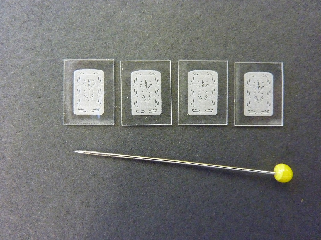
These are laser engraved on 1mm perspex and really lift the appearance of a Highland coach, as you can see:
Sadly, I have also had to increase the prices for most of the products. The costs of the last few deliveries from my etchers have been eyewateringly expensisve, so I need to defer a degree of this. The good news is that this is an indication that more products will soon be featured too – so Highland and LMS modellers keep an eye out.

More Filthy Wagons
Weathering is not something that I find comes easily to me, especially where it needs to be subtle. However, what the OTCM lads have taught me is that unsubtle weathering is easier and a lot more fun! So I have been unsubtle and making a few POs filthy; I wanted to leave the impression that they have seen few decades of hard work and I am really pleased with the results.
All of these have origins in Bachman RTR minerals but with replacement chassis from Colin Welsh’s range (available via the Scalefour Stores – members only I think, so why not sign up!) and some replacement axleboxes from Rumney Models.
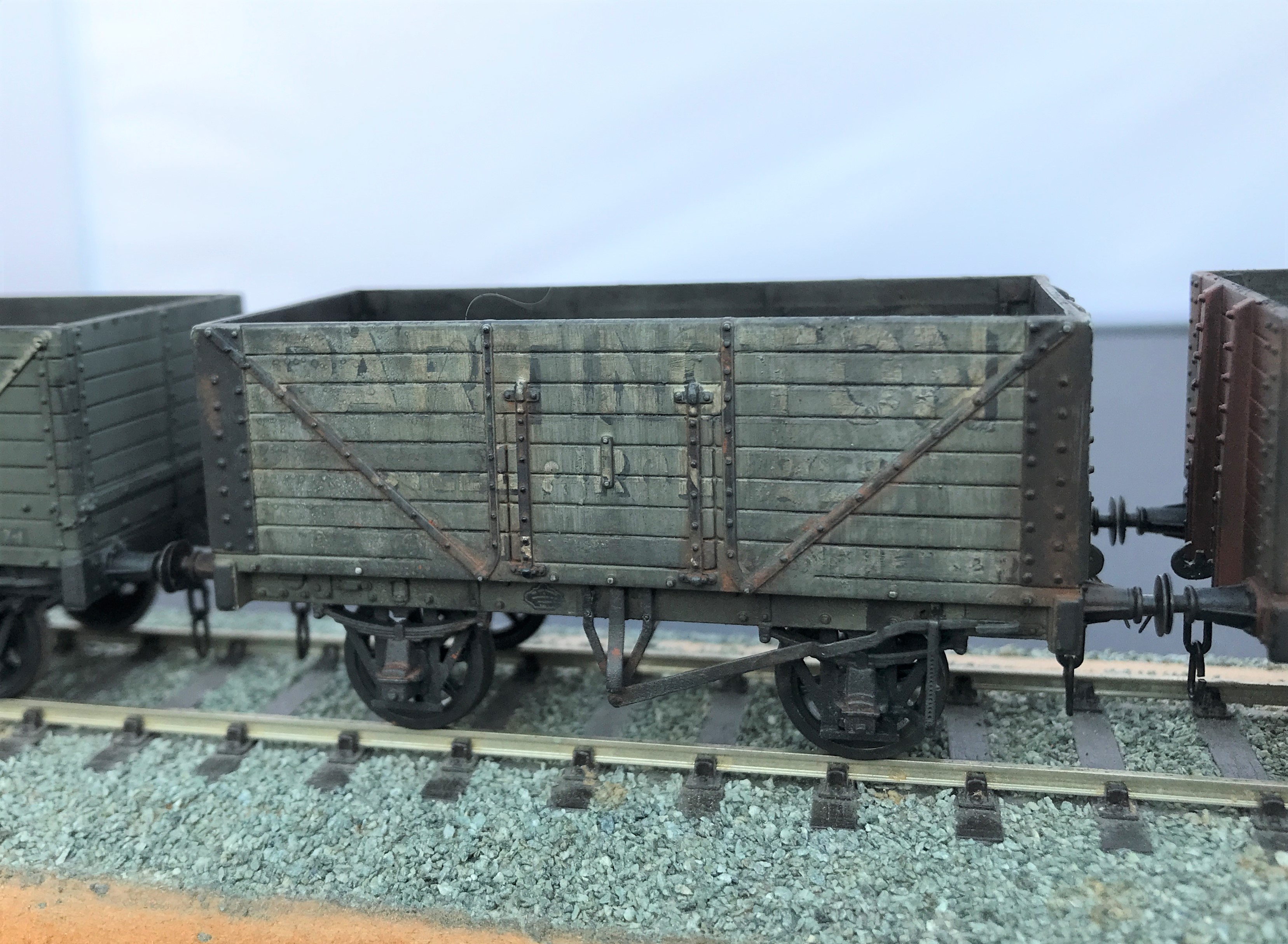
I started with the fibreglass brush to thin down the lettering to give it the feel that it is close to wasted away. Then I sought to represent plank replacements by painting out a few of these with a grey and then added a little texture with dry brushing with track colour (although ultimately the weathering was so heavy this subtly was not worth the effort). The same was undertaken to the insides of the wagon.
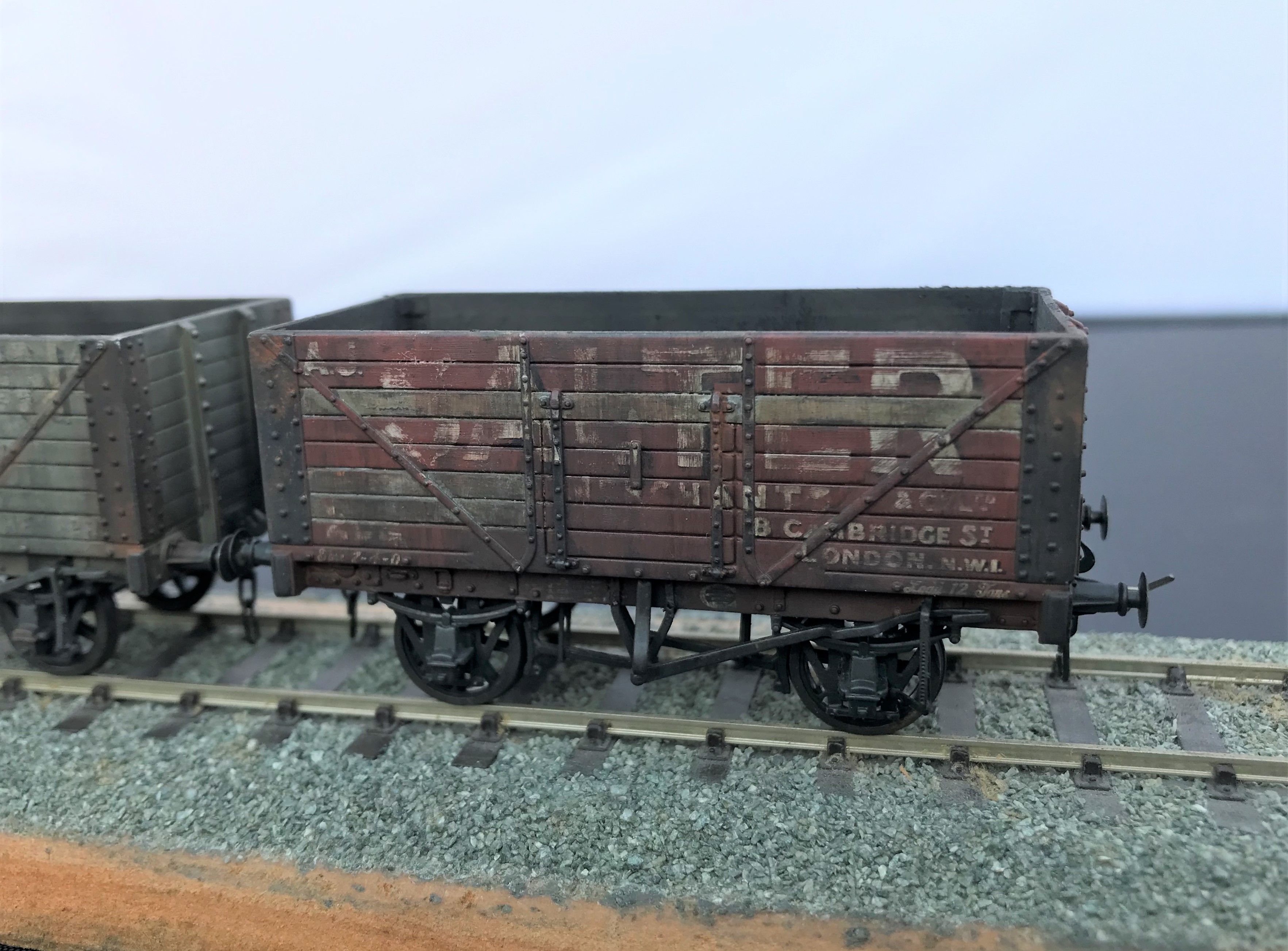
The weathering was completed by a mix of enamel paints; based on black and leather. I started with a lighter colour mix of 2:1 leather/black but then darkened this as I felt that a coal mineral would be a much darker mucky colour so reversed the proportions.
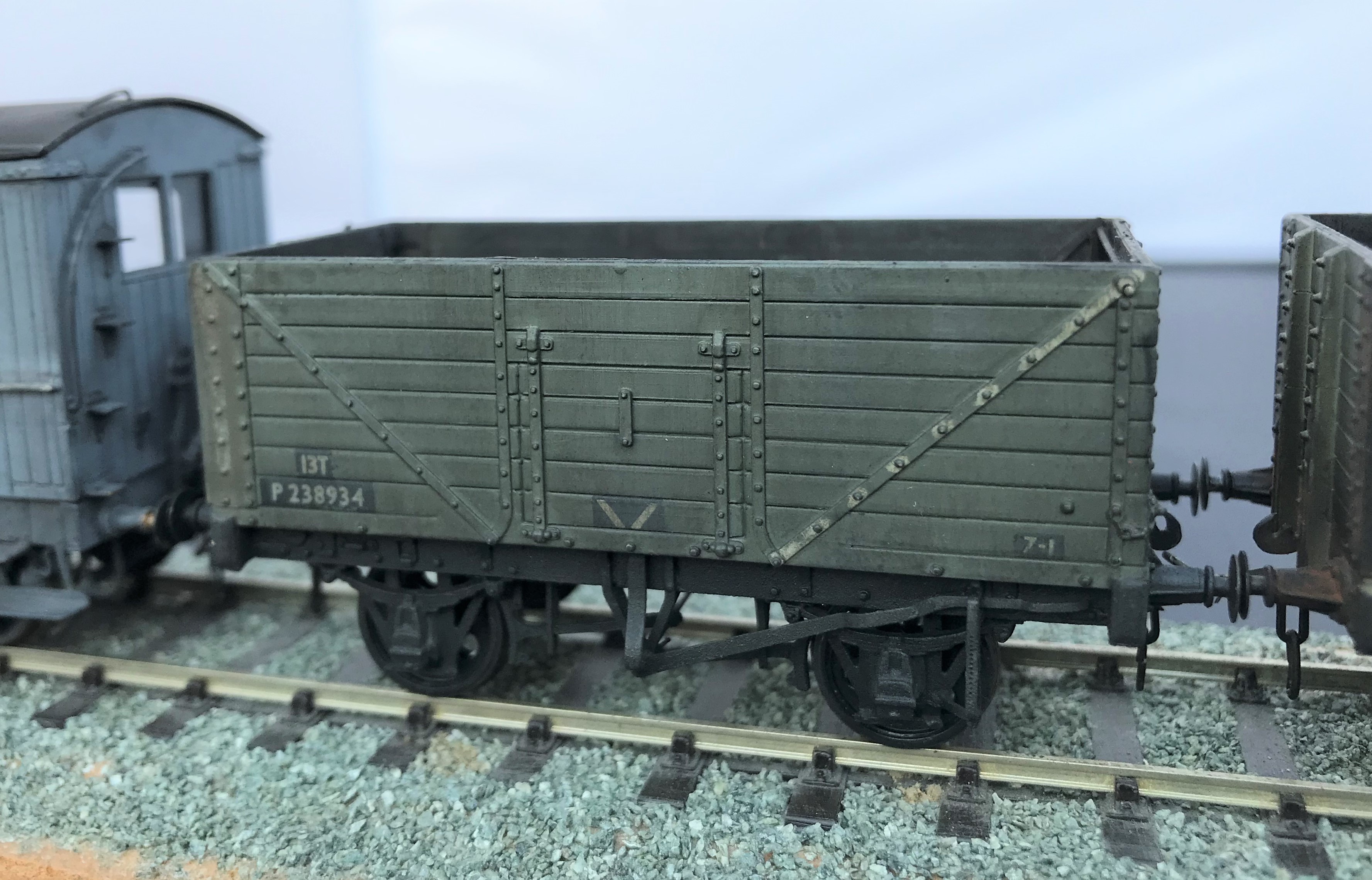
I did these over multiple coats under a very bright light, as otherwise you don’t really know whether you have put much paint on when it is deliberately so thin. The streaking is achieved by using a relatively large flat and stiff brush dipped in thinners. Don’t apply this straight into the model, rub it on the back of your hand to remove the bulk of the thinners and get it down to “slightly moist” before applying it to the model. Make sure it is drawn down vertically, to mimic the movements of water running down the wagon sides.
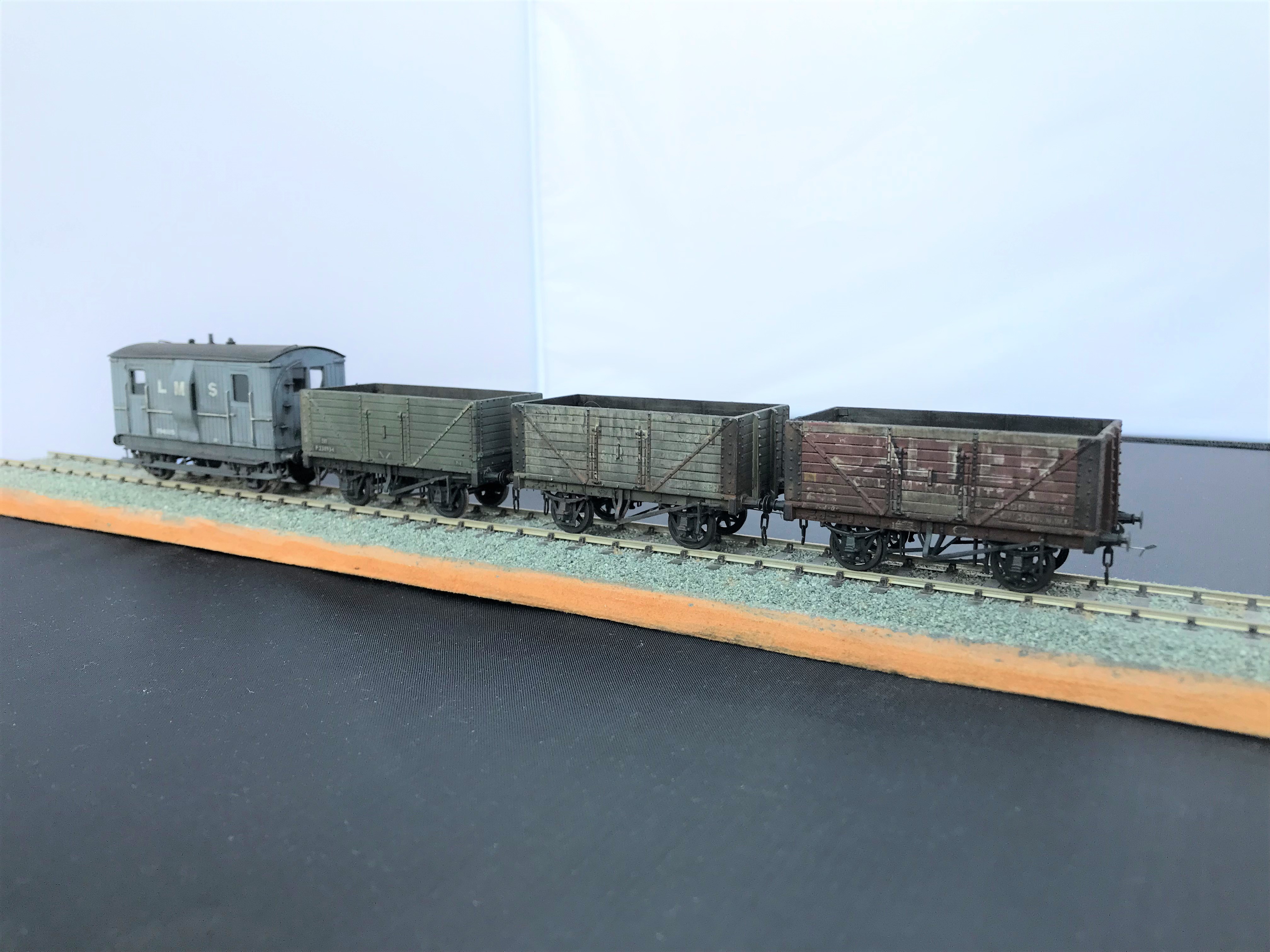
The final stage was then to use weathering powders, rust on the metalwork (mostly on the Partington grey wagon) and black soot. Very small amounts are put on the brush and then speckled on the model with the lightest of pressure because if you blob it straight on it tends to be rather heavy in the points of contact, so it gets a bit blotchy as a result. However, if this is the effect that is required – for example on the top of the buffers for me – then blob away! The powder is then spread across the model with the brush, the more pressure tends to deepen the colour but throughout the powders matt and draw together the underlying colours.
The coal effect in the interior was completed in a similar manner, but with a lot more powder is used and laid on the base a small amount coal dust secured on a matt varnish to leave the impression of a not quite well swept floor from the previous load.
The Other Benfieldside
To date, the images and details I have shown on Benfieldside have related to the main and original station. However, there is more!
Benfieldside’s original builder, John Wright, constructed a significant extension a few years after completing the core layout. This was shown at the time in the Model Railway Journal (issue 57, 1992) and has not really be seen since.
When John’s interests moved on, he disposed of both parts of the layout and in turn the new owner decided he did not wish to retain the whole. However, he elected to retain the extension in order to convert it to P4 as his home layout (Benfieldside was all constructed as an EM layout). We all know what life is like – jobs, family life and other priorities get in the way but progress is now being made. The two main lines are now operational, as these two videos show.
The new layout will be NER as a core, but with also a Midland presence. It appears that the Midland has provided the motive power for the test train!
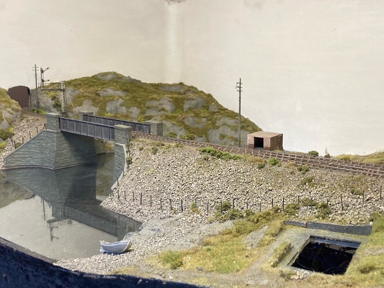
As you can see, Benfieldside’s extension was centred around a substantial viaduct with a degree of siding to one end. Its owner is proposing to make a small MPD here, the beginnings of which are visible in the videos.
There is still a way to go both in the adjustments around the MPD but also in refreshing the scenery. But never the less, as you can see it is another impressive layout.
Portchullin Goes Green………….Again
Fear not, this is not an announcement that the McRats have been converted from DCC to run on ethanol (although this remains the preferred fuel of the layout’s operators). Instead it is a recognition that after 13 years on the exhibition circuit, Portchullin was getting a little faded and even battered. The colours of the vegetation were fading and the woodwork was showing all the miles they have been lugged about in the back of a van – all in all it was looking like 1970s BR, just not in the right way.
We reached the conclusion that something needed to be done about it and in anticipation of an April exhibition invite, the gang arranged a session on the layout to give it a spring refresh. Sadly the show had become a covid casualty by the time we met up but we convened anyway and even the stone-cold hearted Pete was showing emotion at seeing us all again by insisting on greeting us all with a hug!
So out came the static grass machine, modge podge and various scenic materials and away we went…….
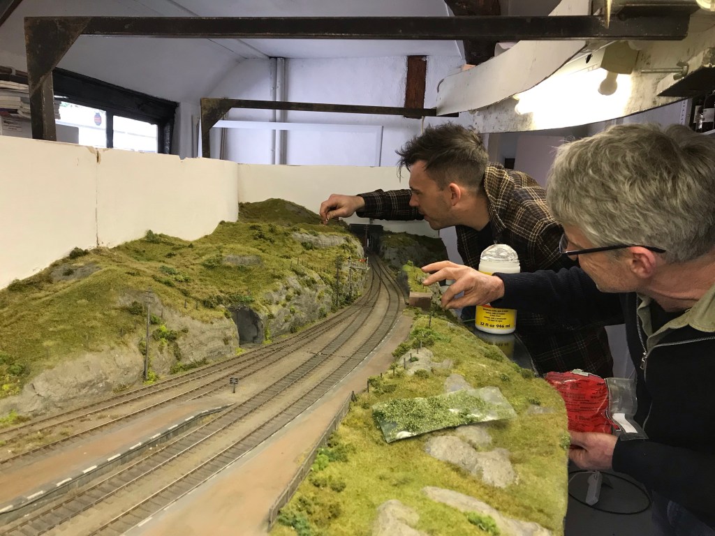
We ended up making quite a lot of difference in only a short while, but adding the dwarf bushes and other vegetation then took a lot of time and I am still thinking it needs more attention.
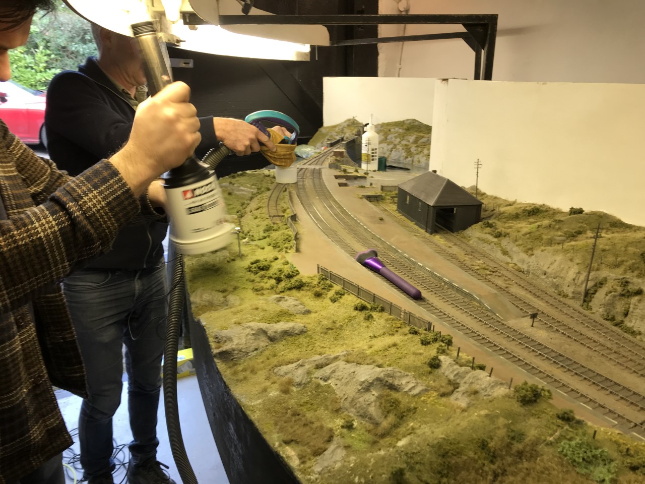
There remains a lot to do, including a revamp of all of the woodshell and lighting gantry, but the layout is looking a lot fresher.
The other main task in hand is a complete rewire. Too often we (well I, the others will have nothing to do with my wiring) have had heads under the baseboard trying to sort out either point-motors or errant wiring, it has to change!
The Other Auto-coach
Some time back I posted about the construction of a NER autocoach that I was building for Benfieldside and subsequently what it looked like once painted by Warren Heywood.
The NER generally used these in pairs, with a loco sandwiched between, although they did go out singly and even as quads. In this case, the Benfieldside team wish to operate them as a pair, as the bay to the right of the layout is conceived to receive such a train, with a NER / LNER G6 in between. This means that there was pressure to build the second from the moment I handed the first over. They have recently given me a favour, so it was high time I repaid it.
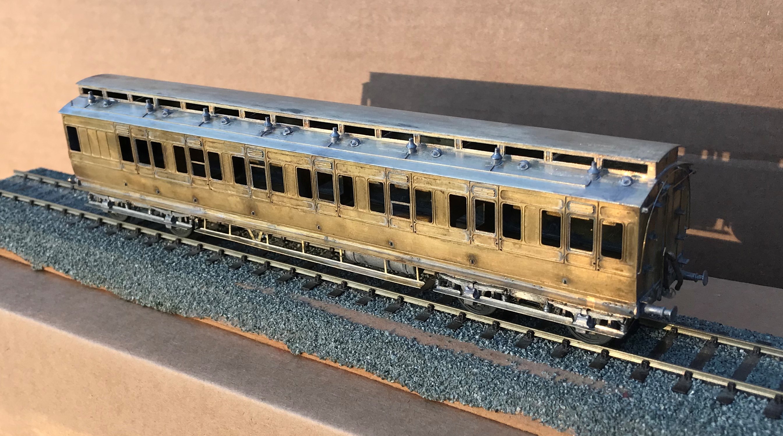
It is now completed down to the final check over stage (which has indicated that I need to put the steam heating pipes on – doh!) and then it can be delivered. So I have braved the fading light this afternoon (so sorry about some of the depth of field issues) to take a few pictures and to prove to the fellas it is done!

I completed a few personal upgrades to the kit in both this and the earlier autocoach. Chief of these is around the roof where I ditched the plastic roof and replaced it with rolled brass. This was formed of 0.25mm to give it a tangible depth, which makes its rolling a fair challenge. Add to this, I elected to cut out the portion below the clerestory, so that it was a clerestory! By the time I had added the gas lines and the various gas lamps and ventilators, I reckon there is around 20 hours in making the roof alone!
The prototype coaches were fairly long lived and numerous. They thus collected a good number of alterations and differences over time. I took some guidance to David Addyman and tweaked the kit in respect of gas lines, foot steps, handrails, footboards and gas cylinders. If someone thinks this is wrong, please don’t tell me!!
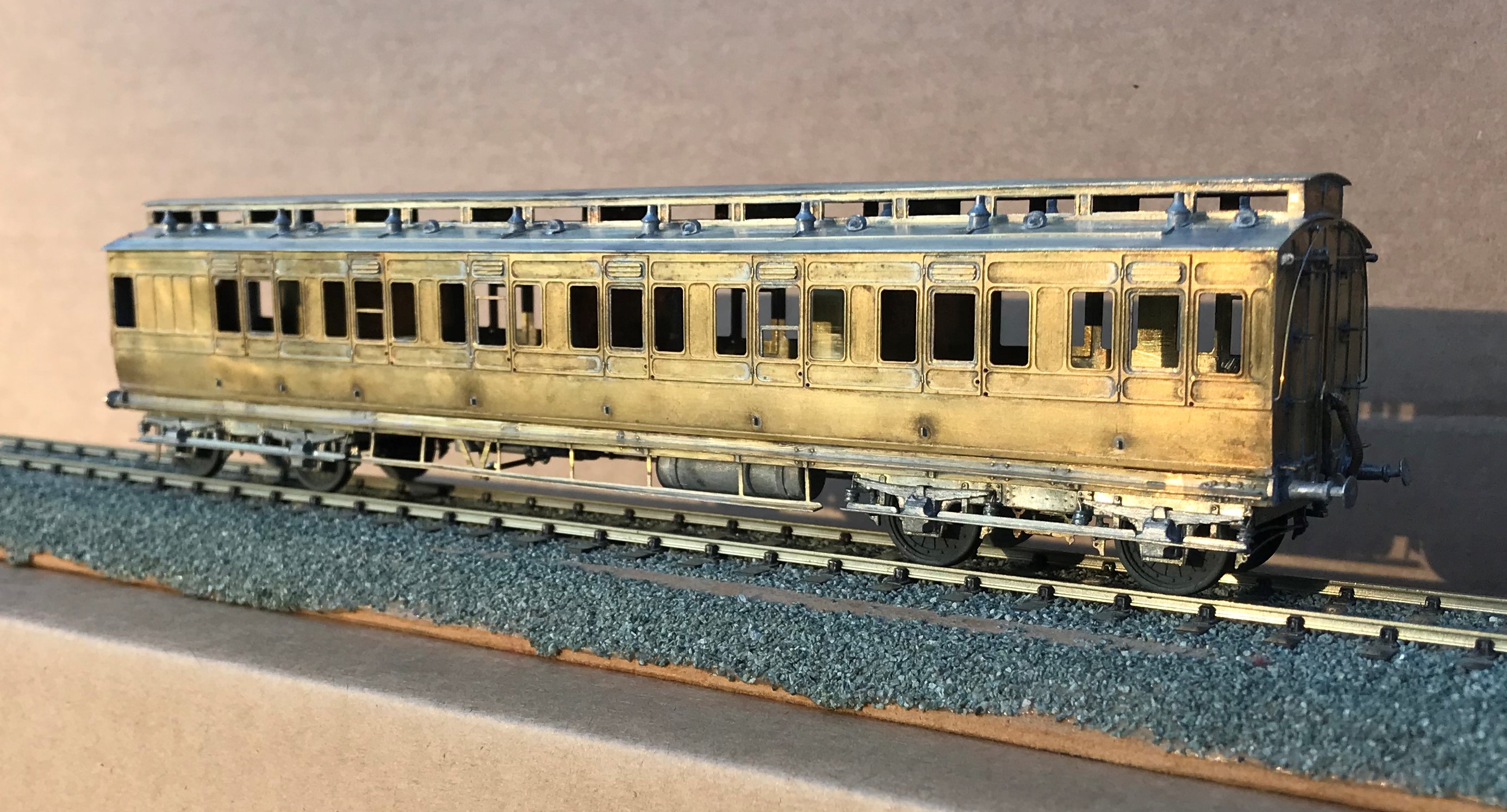
It always amuses me that the driver had to stand and peer down the line through two tiny windows. They lived in different times – could you imagine the snow-flakes tolerating this in the 21st century?
These are rather beautiful coaches, but not for the feint-hearted as there is a lot of time invested in these. I am pleased I do not have to paint it!

A Fold of Cattle Wagons
Your pub quiz fact for the day is that the collective name for Highland cattle is not a herd, as it would be for most cattle. Instead, and only for Highland cattle, the collective name for a group of cattle is a fold. If that does come up in a pub quiz, you owe me a pint!
Cattle were an important part of the highland economy and hence were a good source of income of the Highland Railway. In my slightly distorted version of real history, there were 4 million head of cattle to transport per annum in the Glenmutchkin area (which is remarkable given the cattle population of the entire UK at the time was only a little bit higher!). Thus, a fold of cattle wagons was obviously a pre-requisite for Glenmutchkin and this is what I have been working on of late.
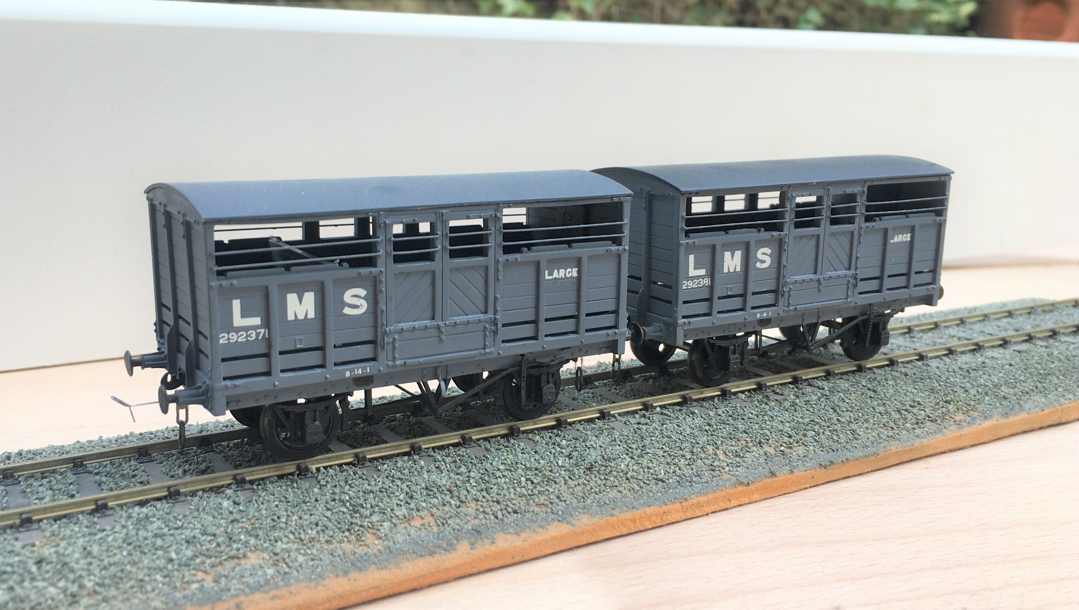
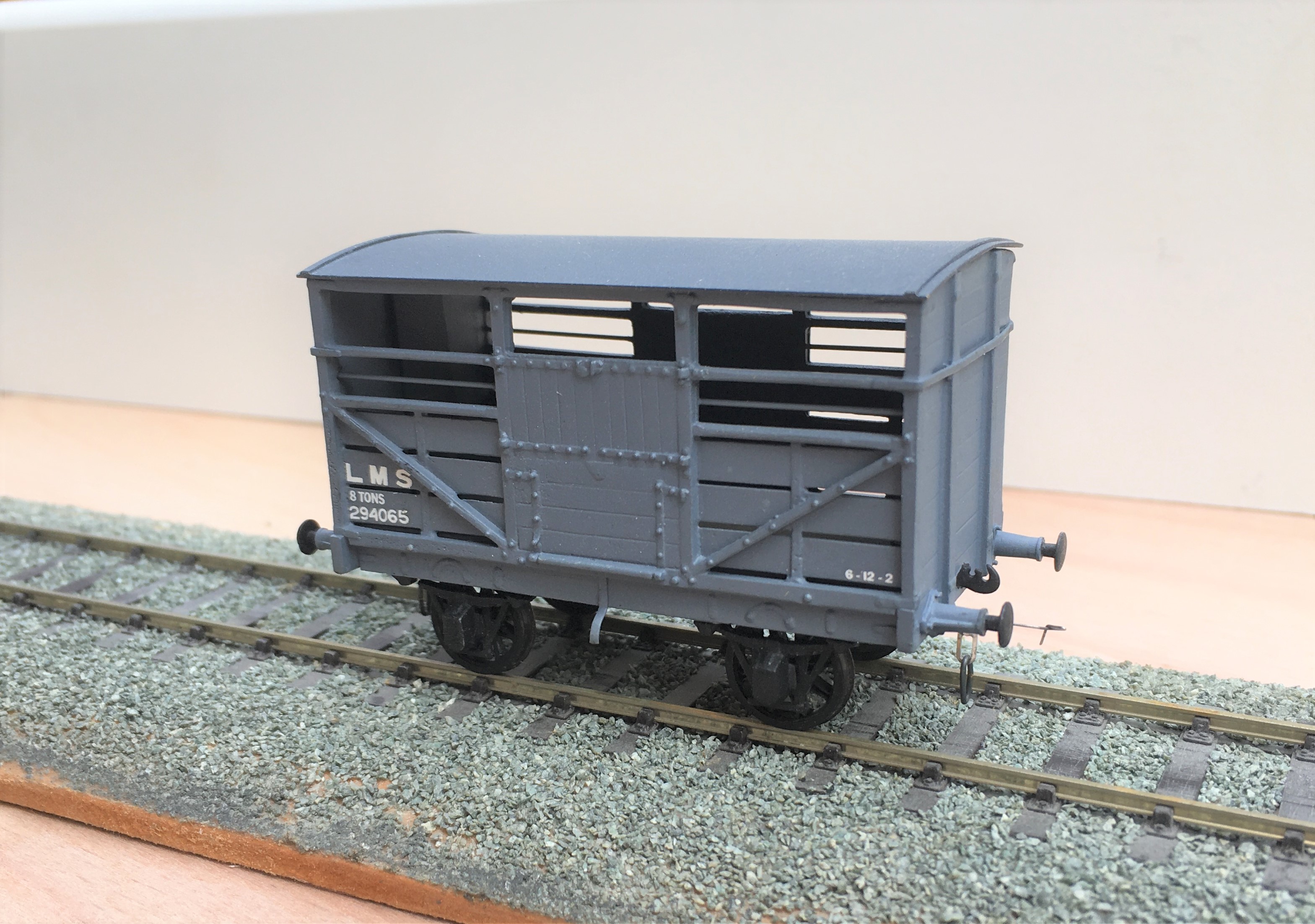
First up are a pair of LMS standard cattle wagons; to diagram 1661. These date from 1925; so they would have been fairly new at the time that my layout is set in. These were built from Parkside plastic kits with only moderate modifications around the break gear and, of course, some sprung w-irons. Being a relatively recent kit, it is generally very good and whilst it is possible to convert it to some alternative variants, these came later than my modelling period so I was not tempted. I am concerned that I have painted them rather to dark though, so I will be weathering them on the light side.
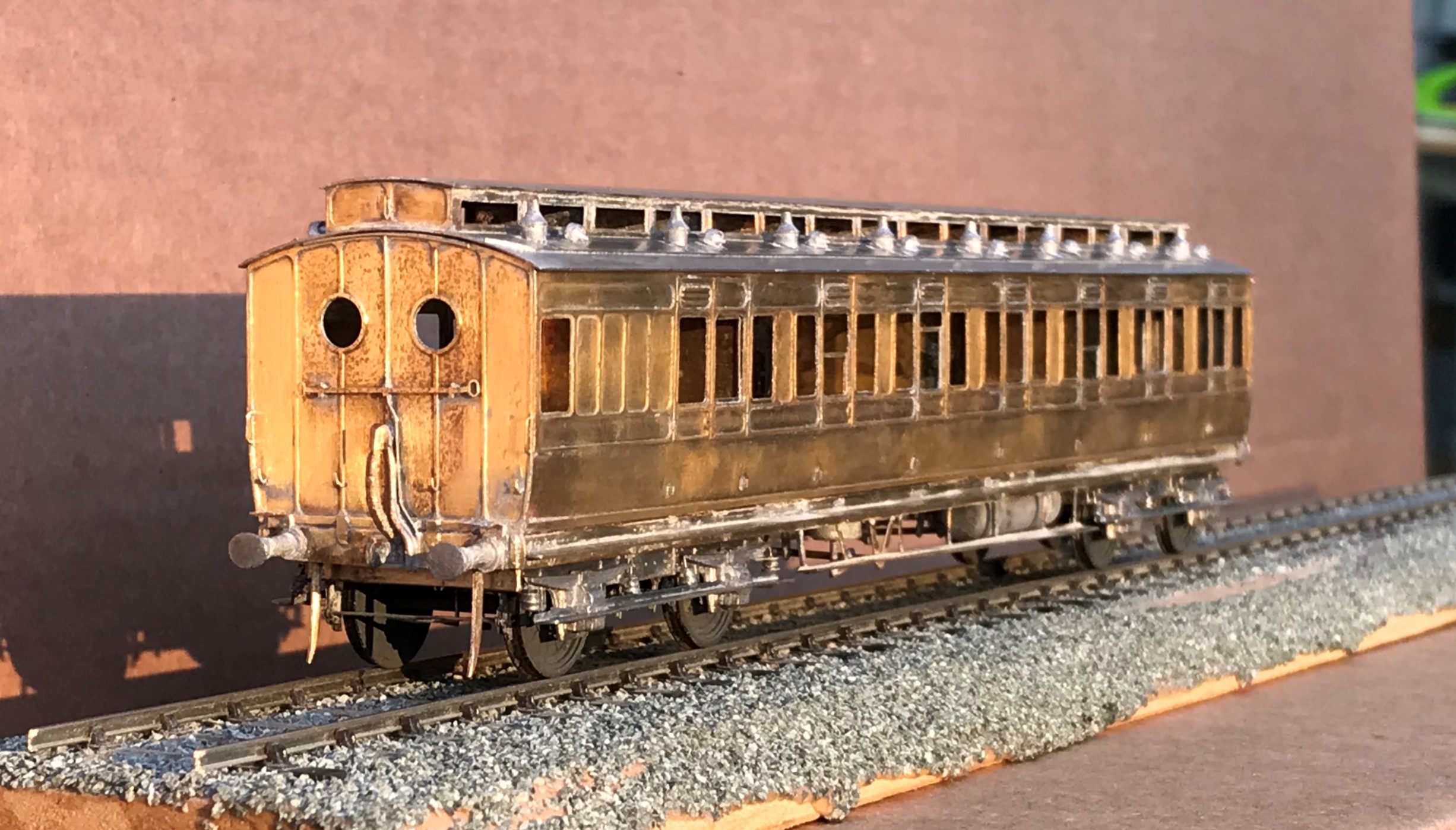
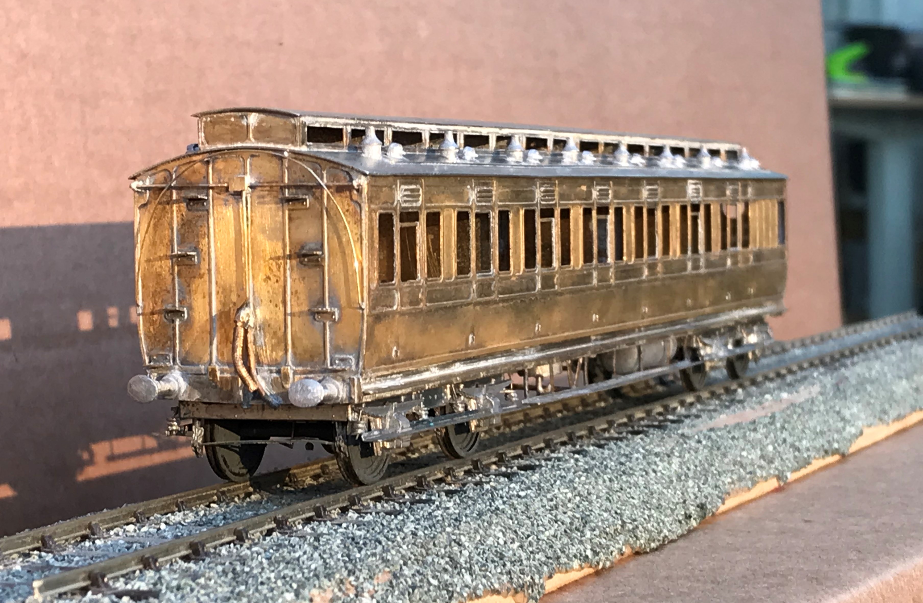
Next up is a Great North of Scotland Cattle wagon, from a Model Wagon Company white metal kit. This is a much older kit and didn’t it felt it! For reasons I am not certain of, the two sides were not the same length so in practise the body is a bit trapezoidal – but can you tell? The casting was also covered in flash which was a particular problem in the gaps between the wooden slats – this meant I spent a few hours I would sooner not have spent scraping it out to keep these clear. The GNoS vehicle was a much more basic vehicle and, strangely, did not get any large ownership lettering so they remained rather anonymous, Instead, they had simple cast plates, which I made from a locomotive number plate and dry brushed white on the letters. I have glossed over the fact it does not have the right number or even a consistent number from one side to the other – sod the “getting it all right” mantra!
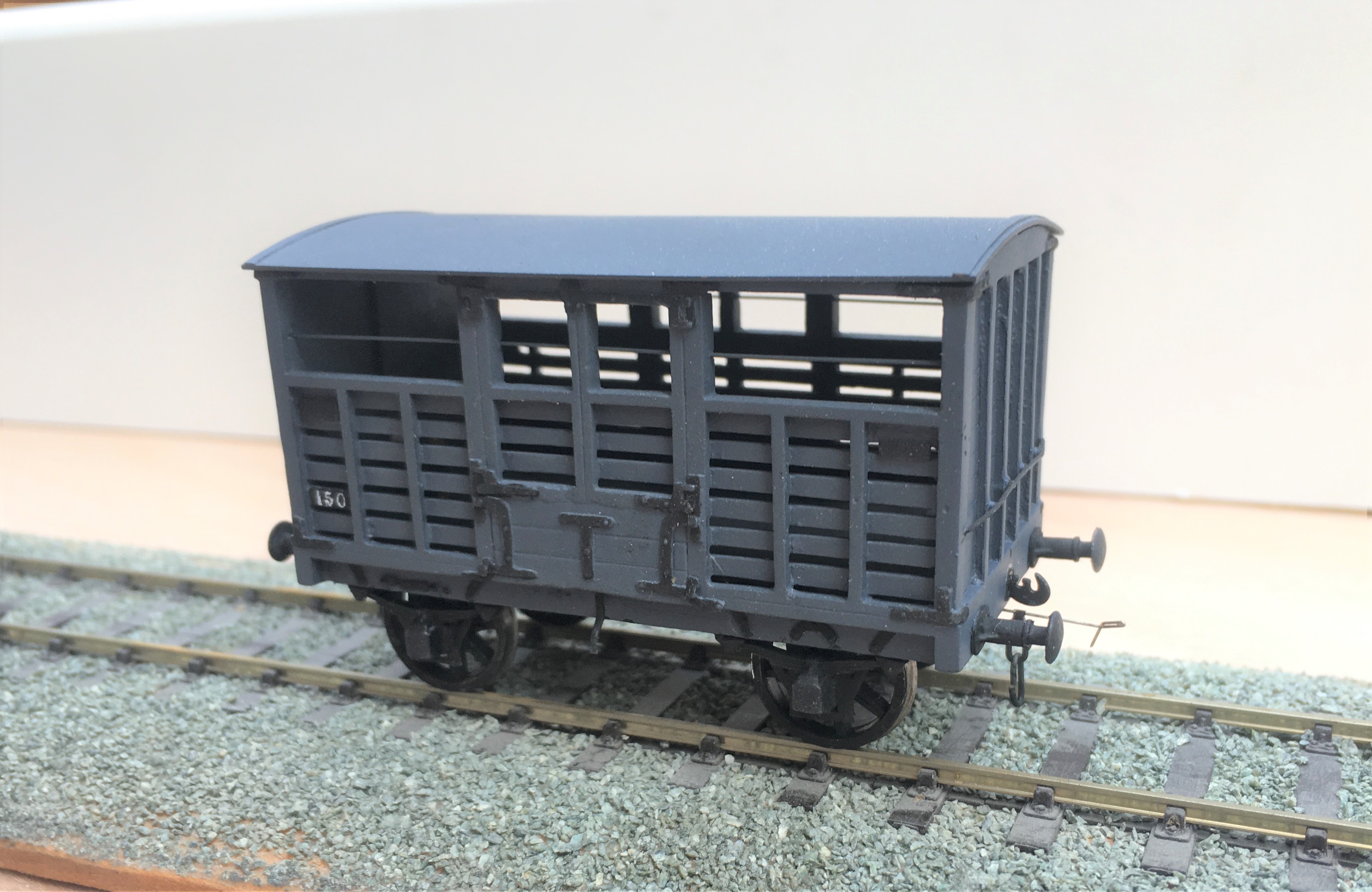
I have also built a further Highland cattle wagon, built from a Model Wagon Company kit. This is the Drummond era version and I have already built a number of these so this was relatively routine – its just as well as there are still a couple in their packet waiting their turn!
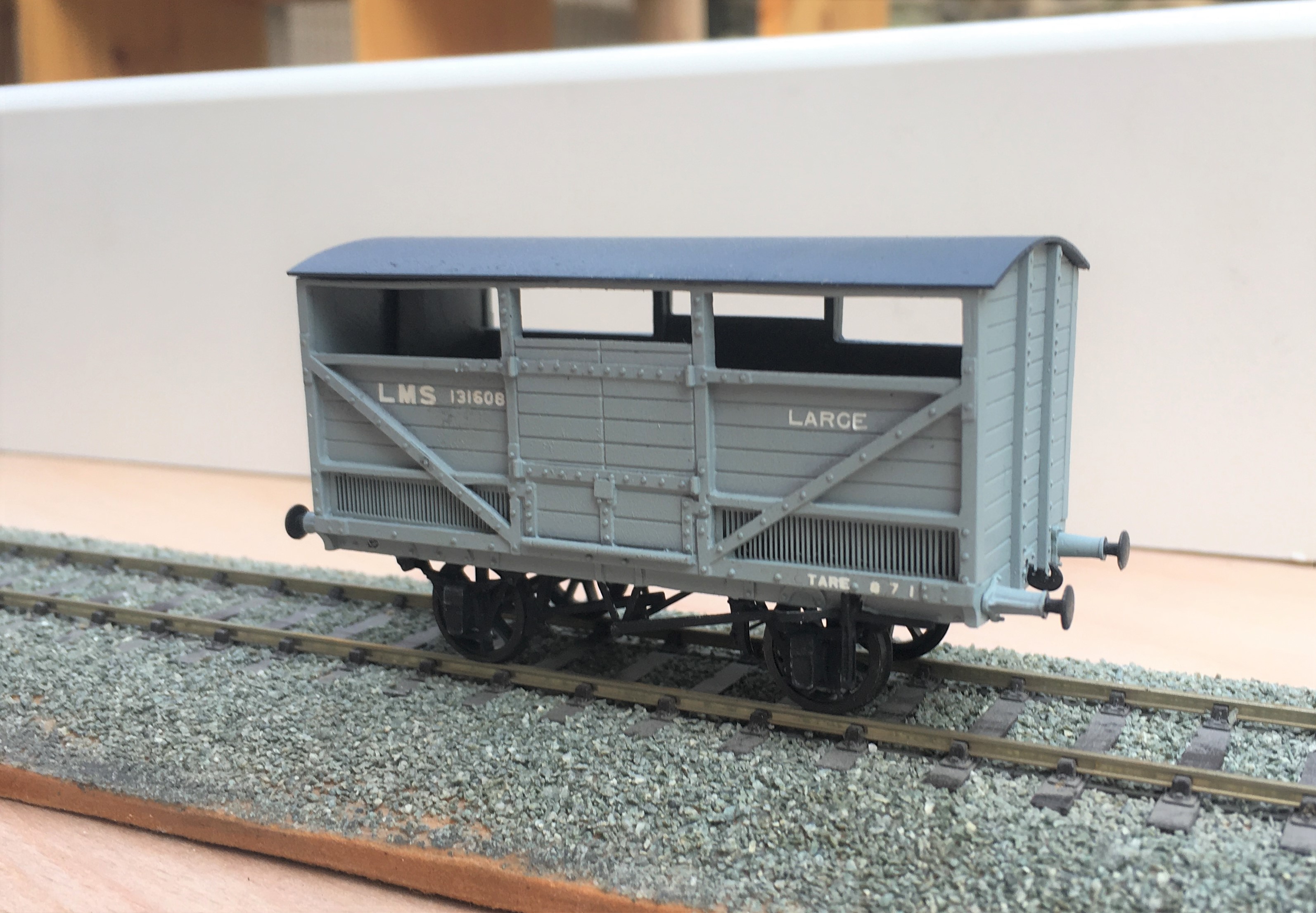
The final cattle van is a David Geen kit for the L&Y large cattle wagon. Whilst still a whitemetal kit, it is of somewhat better quality than both the Model Wagon Co kits so was rather easier to make. Even then, it did need filling at the corner joints and I felt the need to swap the brake levers for replacements – why to even the better manufacturers use the same material for all of their kits?
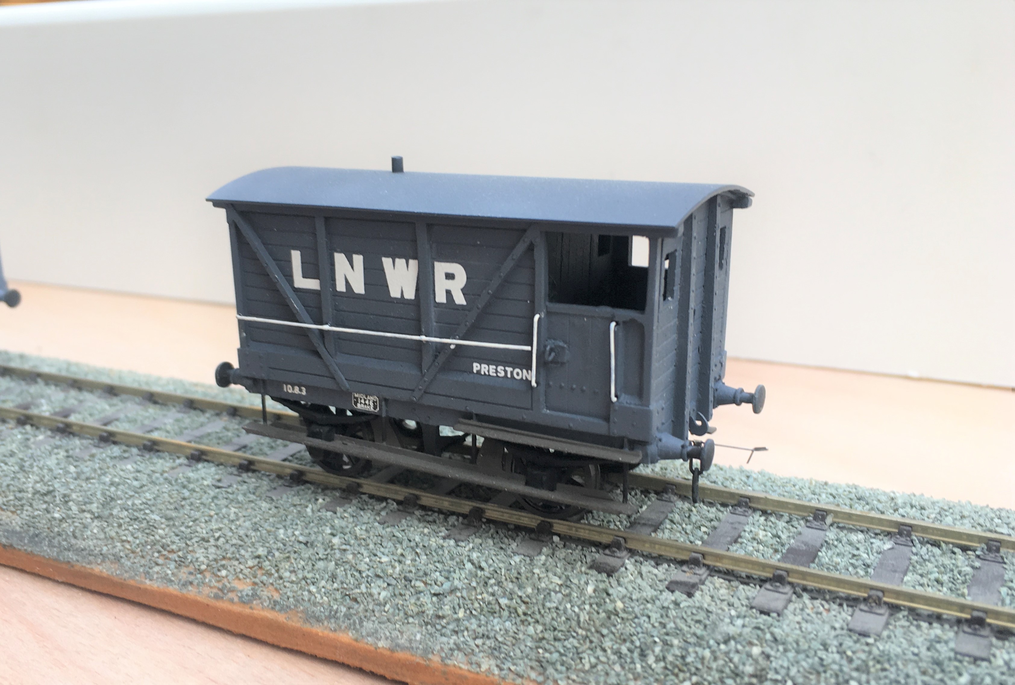
To finish of this little rake, I obviously need another brake van. This is not so obvious because this is brake van no 11 in the collection and I know I have at least one more spirited away! Whilst this was a kit build, it was first a kit unassemble as this was a vehicle I had first built in my teens. Generally fairly well but a couple of bits had got damaged over the years so I felt it needed rejuvenating.
And here they all are on parade.
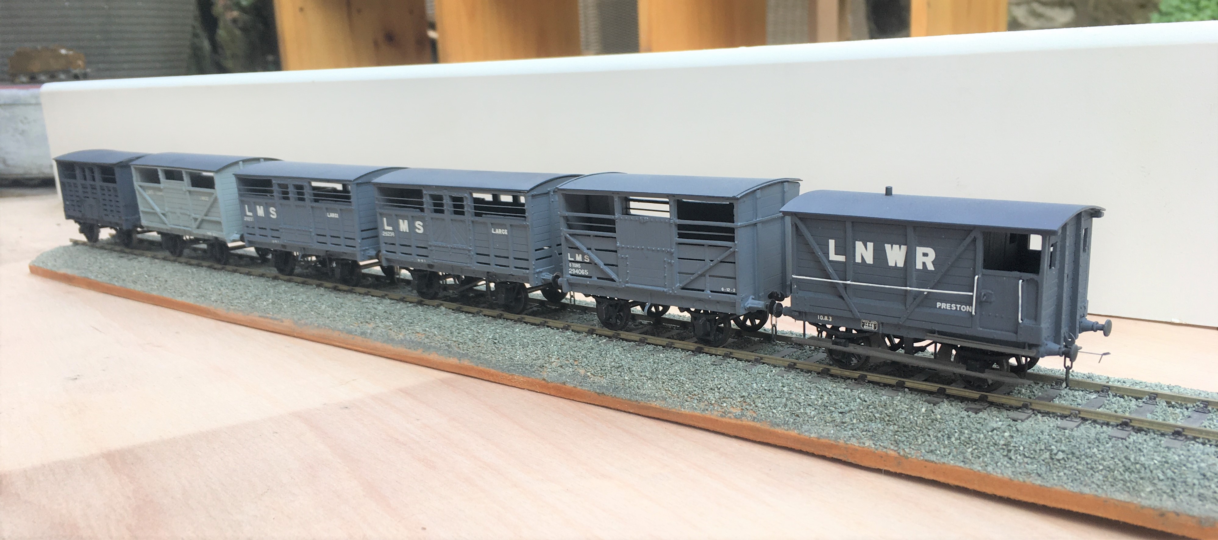
Now all I need is rather a lot of heilen coos to fill them up with. I have been working on this but it seems that resin casting is a tad more difficult than I thought……………..
Oh and yes, they are all way to clean; another weathering sess’ is required guys………..
Scaleforum at a Screen Near You Soon!
With these strange times that we have been experiencing for the last six months, we have all become a bit cooped up in our abodes. Whilst the lack of model railway exhibitions is hardly going to make the six o’clock news (can you imagine!), I for one have missed both the inspiration and the camaraderie they offer.
We have not seen a plethora of on line exhibitions so it is welcome news to see the Scalefour Society making the effort to arrange one in place of their annual exhibition. This will “take place” on Saturday 26th September between 10:30 – 5:30 although it seems much of the content will be available thereafter online. Here is a trailer for it:
In addition to seeing familiar faces again, I was particularly struck by the possibility of seeing a number of “home layouts” that we don’t ordinarily get to see – and some big ones at that!
Some seems to be by video and others by an interactive youtube link so that you can chat to the team/person. This is the listing of what is proposed.
Layouts:
Boston Frodsham by Mike Knowles
Bristol Barrow Road by Robin Whittle
Central Cheshire Lines by John Sherratt
De Graafstroom (P87) by Vincent de Bode
Drighlington and Adwalton by Steve Hall
Eridge by the Kent Area Group
Faringdon by Rex Davidson and Stephen Williams
North Elmham by the North Norfolk Area Group
Obbekaer (P87) by Geraint Hughes
Pwllheli by Jonathan Buckie
Southwark Bridge by Mike Day
United Mills by Ray Nolton
Demonstrations
Adrian Musgrave – Signals
Alistair Ford – Timber Buildings on Black Gill
Brian Hingston – Coaches
Chris McCarthy – Baseboards
Dave Keeler – Wagon Construction
David Brandreth – Resistance Soldering
Jim Smith Wright – Soldering White Metal
John Farmer – Scenics
Mick Moignard – DCC Sound
Nick Rogers – Wagons
Rod Cameron – Lewis Project
Stuart Holt – Tree making
Illustrated Talks
Martin Nield – Authentic Model Railway Operation
Jim Summers – ‘Earning a Living’
I can see that chunks of the readership of this blog are dispersed in far flung places – take some time to see some really good 4mm without burning your air miles. The details to the log in can be found here:
So I know what I will be doing with much of the 26 September…………………. I will even make sure I have done some on-line shopping at about the same time so that Scaleforum hits my pocket in the same manner as usual!!

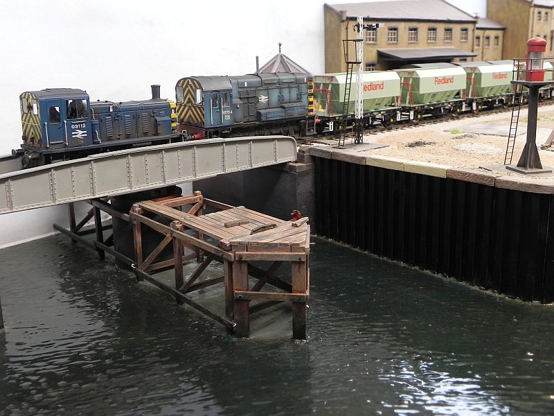
Fuel for Thought
Obviously, where there is water in a locomotive yard, there really ought to be coal too.
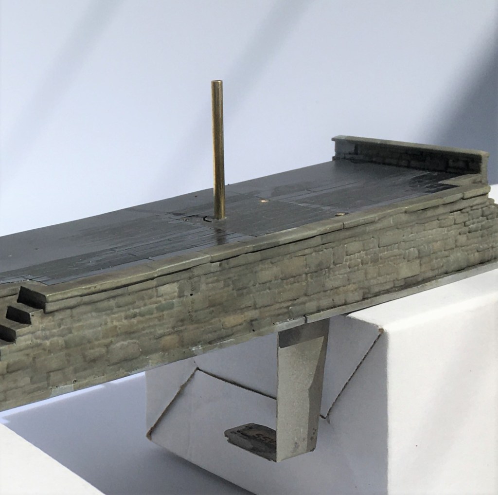
The Highland, like many other railway companies of the time (certainly the Scottish ones), sought to stockpile coal. This was presumably insurance against coal strikes and allowed them to purchase coal at times when the price was favourable. Thus, quite substantial coal stacks where very much a feature of shed areas in the pre-grouping era. Typically, these were arranged in engineered stacks, with the sides formed in “dry-coal walling” and then loose coal behind. I can’t recall ever seeing this modelled, so I though I would change that!
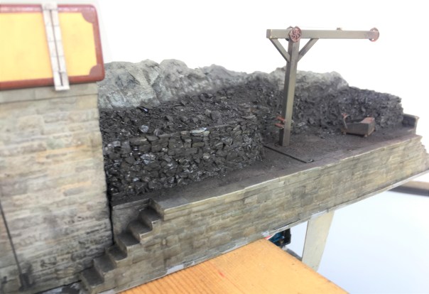
The actual structure of the loading bank was formed in plasticard and Wills random stone sheets, but with the mortar courses softened as I described for the water towers. The shape of the coal stack was formed with a piece of house insulation left over from a DIY job and then real coal used to form the effect of…..err……real coal. Actually, real coal does not look quite like real coal without a bit of effort. It does shatter into angular but irregular lumps like real coal (especially if lignite coal is used) but its glossiness does not scale down. However, a vigorous brush with generous amounts of soot black weathering powder takes the gloss back and the whole becomes quite convincing. You do feel as if you are going to get pretty filthy if you go up onto the bank – and until the whole is fixed with matt varnish, you would!
Individual coal chunks were glued in place to form the wall structure. To get the effect, it is not enough to simply scatter the coal onto a bed of glue each chunk has to be laid individually with care taken to lock it into the course below – just like a real dry stone wall. Thus, the vertical walls of this took about a day to complete, scattered over about 8 stints because it is necessary to let the glue dry after every couple of courses to stop the layers collapsing. It is then possible to scatter the loose material behind the walls onto a layer of glue – the above picture shows the contrast in effects between the two methods.
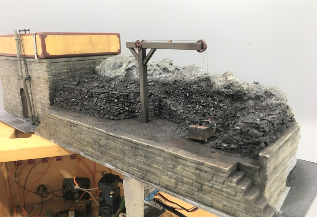
But it is hard work shovelling coal into tenders, especially as the locos got larger and their tenders higher. As befitting such an important place as Glenmutchkin, it has all the modern amenities for coaling engines, a hand crane and a large bucket! In this case, I have fitted servos to this so that it operates – partly as a bit of fun and also to slow things down in the yard to a more realistic pace without it getting too boring for the viewer.
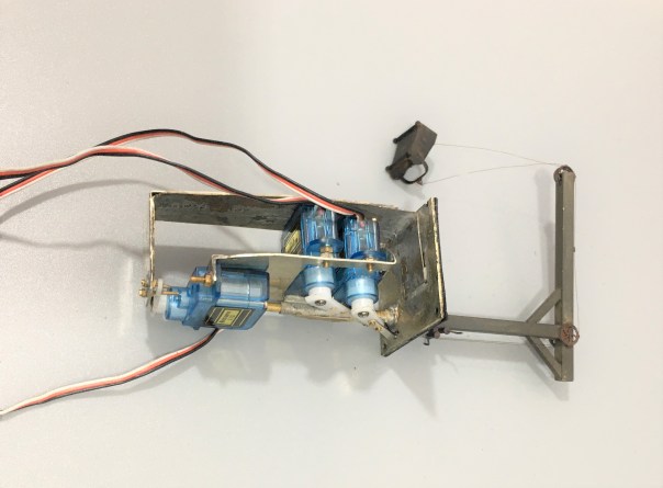
The crane operation was achieved by way of three servos – one to rotate it and then one each for the front and rear of the coal bucket. These are all mounted onto a cradle that is rotated by the former – thus as the crane rotates so too do all the servos and there is a quadrant shaped slot in the base to the rear of the post (just visible in the picture above) that allows the cables to rotate too without snagging.
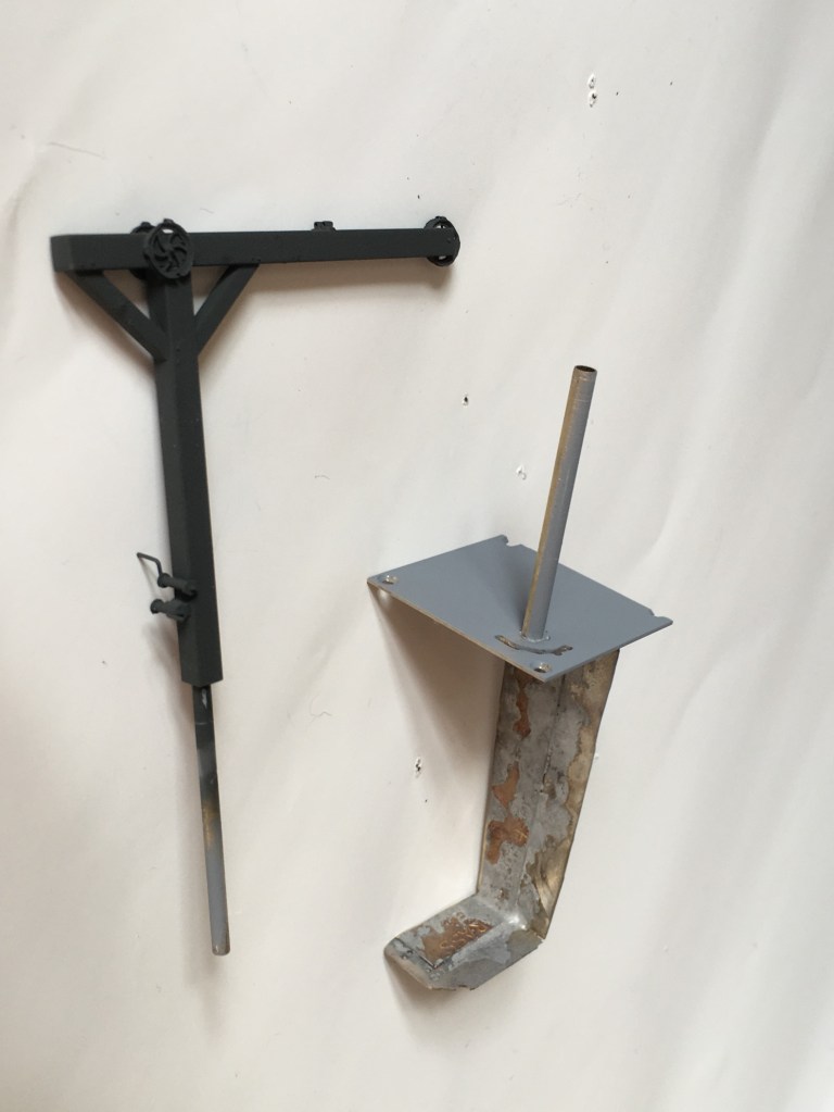
The cradle is mounted to a solid rod that is in turn secured to the actual crane. This then slides into the rod that can be seen projecting from the base in the picture above. This means that there is limited strain on the crane or the mount as I had feared it might otherwise snap with any heavy-handedness on my part (something I am prone to!). The rest of the crane was made with brass hollow section and pulley wheels from Bill Bedford. A series of guides were made of small section tube on the pulley wheels, at the winding drum and across the jib to retain the operating cables.
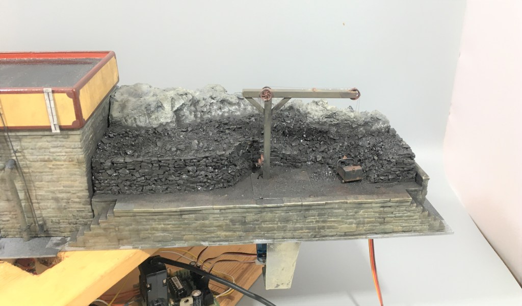
The bucket was fashioned from metal sheet and is filled with low melt solder to give it as much weight as possible. It is secured to the servo arms with invisible thread – which is a nylon seamstresses material used for making invisible stitches. It comes in both clear (which really is invisible) and black, I used the latter. It is much better than cotton thread as that has a furry finish that looks terrible after a time or if it is painted. It is, however, very fine and rather wriggly to knot, so using it involves a certain amount of cussing!
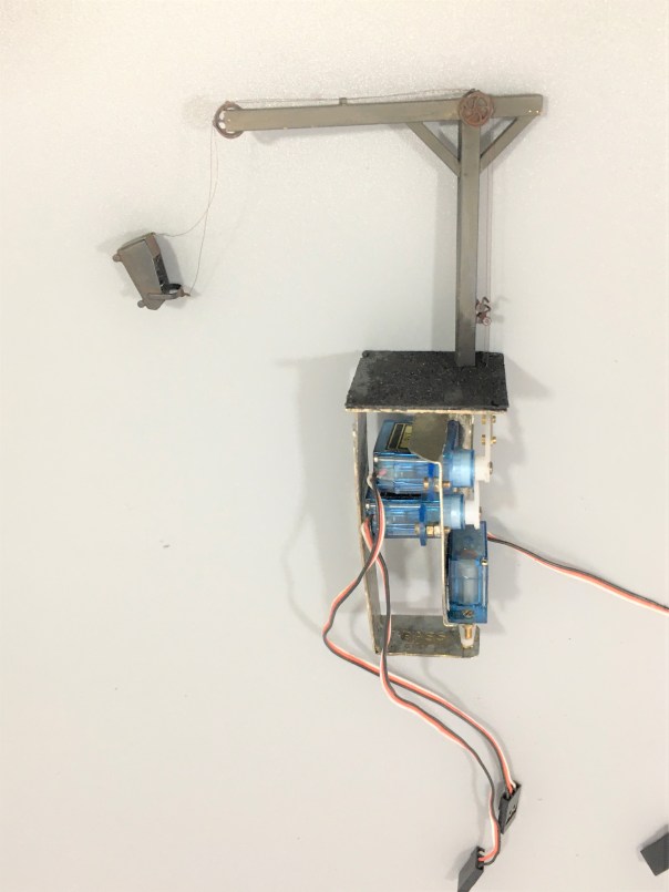
And this is what it looks like in operation…………
A little of the bouncing about of the bucket is caused by it sitting on my servo test rig, so the act of changing the switches imparts a little vibration. Hopefully, when mounted on the layout this will be less obvious.
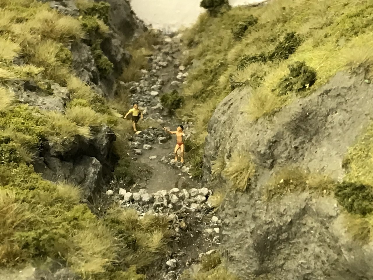
I do still need to do the final detailing on this; tools, a bit of discarded debris and a couple of fellas from Modelu standing around doing nothing (because static people in animated poses look silly on a model layout!).
