Blog Archives

Controlling Bottom Works Sidings
Followers of this blog will probably be aware that I share some of my model railway escapades with the two authors of the blog OTCM. Both of the authors are in the process of putting together entries into a competition to build cameo layouts being orchestrated by the publishers Titfield Thunderbolt. Cameo layouts was the topic of a book written by Ian Rice and seeks to describe a small layouts seeking to use presentation techniques to capture a slice of the whole in a convincing manner.
To be fair to Oly, his entry is largely complete as long as he does not seek to tinker with it too much(!), the same could not be said for Chris’s entry – titled Bottom Works Siding – so he has some catching up to do! To assist Chris I offered to make his signals and after a few weeks of work we have reached the point where they are complete.
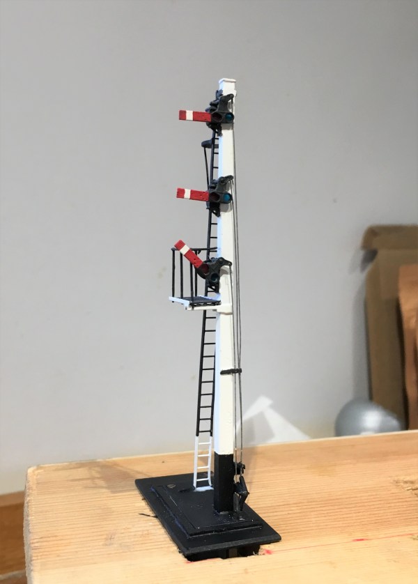
Chris’ model is based on the GCR’s route over the pennines at its Yorkshire end. It will represent a set of transfer sidings from the Woodhead route electrification to a industrial line serving a coking plant – so I suspect we will get to see a fair amount of grot in the finished article! Its signals are LNER or BR(E) practise which is mildly different to what I have built before in some regards but not others as there was a lot of standardisation between the LMS and LNER (and BR more or less adopted LMS practise). So first up (above) is an LNER standard wooden post with replacement BR miniature upper quadrant arms. The post is a piece of brass square section that I filed to a taper (hard work) with predominantly Masokit’s fittings (which I found to be notably better than MSE’s equivalent).
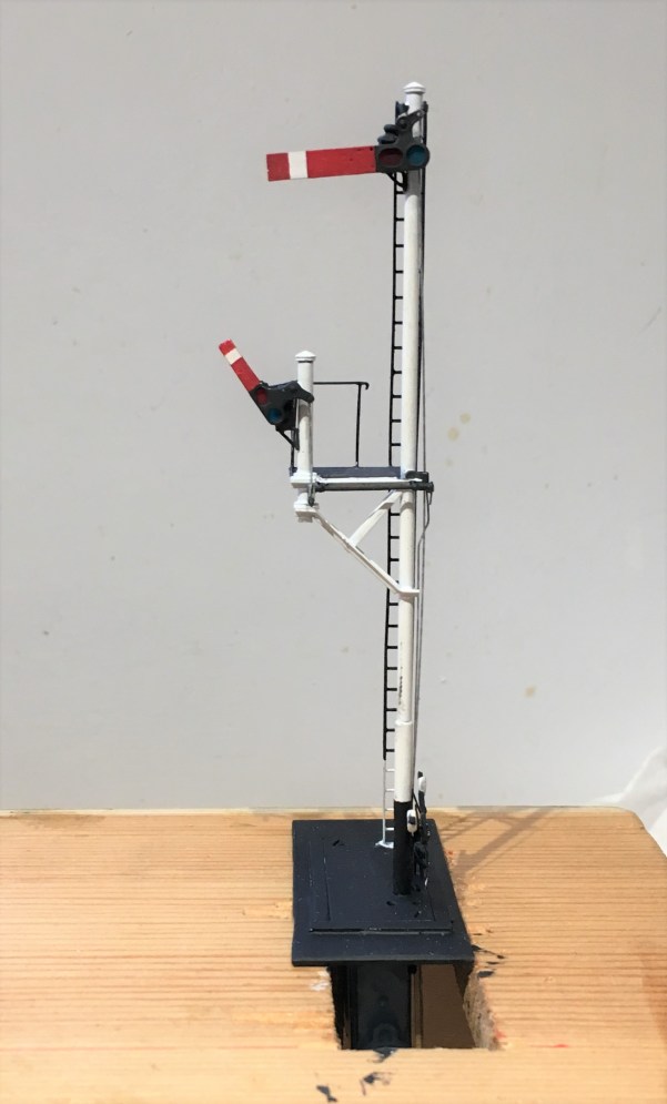
This one is effectively a standard LMS/BR tubular post signal (apparently with brewer’s droop – sorry!) with a small bracket that has another miniature arm signal to it. This is assembled with a combination of tubes and angle section from Eileen’s Emporium, along with some more Masokit’s arms.
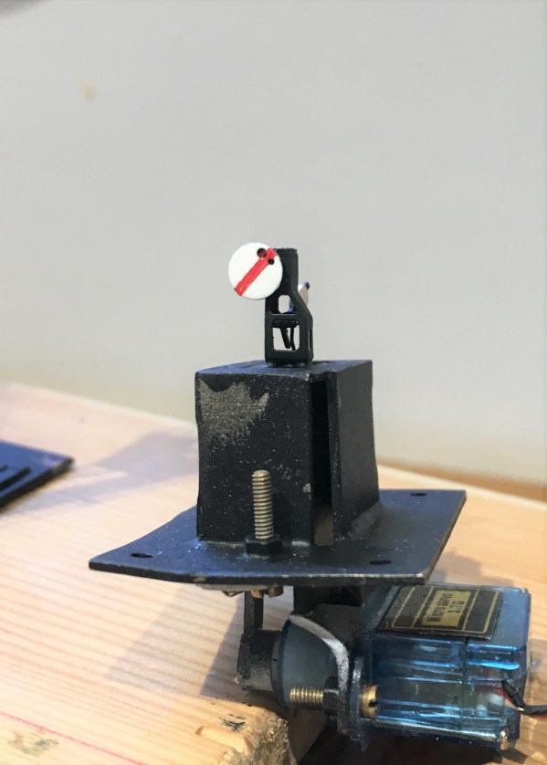
And finally a miniature ground signal – which despite being startling small was not actually all that difficult to build – it being based on a excellent little etched kit from Palatine Models.
As a result of a lost camera, there are not really any meaningful photographs of the signals being created but fear not, I still have a few to go for Glenmutchkin, so there will be some to come! In the meantime, and to prove that they really do go, here are some videos.
In the fullness of time, I dare say we will get to see these in situ, so why not subscribe to Oly and Chris’ blog, to get an instant notification?

Cornish Modelling and the Demon Barber of Fleet Street
Don’t worry – this is not announcement of being turned to the dark side of modelling “Green With Rivets” (aka the GWR)! Instead it is a reference to a week’s trip to the extreme west of Cornwall to support my wife who was appearing in a musical that was running for a week at the Minack Theatre – more of this later……
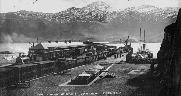
As I was expecting to have a degree of time hanging around whilst the Mrs was on stage, I took a little modelling with me – in this case, a Jones era double deck sheep van. As can be seen in this George Washington Wilson photograph of Kyle – sheep traffic was an important source of traffic to the Highland Railway – the majority of the train in the platform are sheep vans and there is also a row of them in the foreground.
Ever with the eye to efficiency, the Highland developed a double deck van to double the number of sheep that could be transported in one vehicle. I believe that the Cambrian Railway and several railways in Ireland had similar vehicles, but otherwise these were characteristic of the Highland’s lines to the west coast and clearly I have to have a rake of them. Unfortunately, there is quite a lot of effort in each one………….for example each side below is made up of five layers of laminate (and they are delicate too)!!
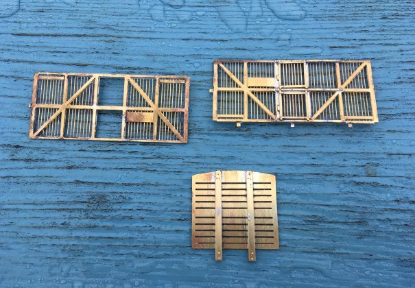
The highland had several versions of these vans, this time I chose the second era of van, which has a single door and diagonal bracing; I do have plans for some of the other diagrams so this is a topic we will revisit at some point! The starting point for this vehicle was an etched kit from the Lochgorm range (presently unavailable, but we are all hoping……) and as already hinted, it is not an easy one! This is mostly due to the delicacy of the parts and the multi-layering of the etches that take up a lot of care to line up with each other. It takes a fair few hours simply to get the sides made up and ready for assembly and then you still have the metal bracing to do!
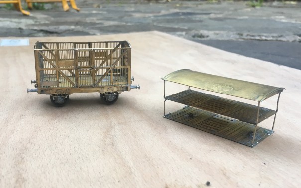
There were a number of elements to the kit that did not work for me. The various tabs you see in the above image are to help locate the various floors with each other but in practise they are not correctly located and just get in the way – so I whipped them off! I also ditched the compensated suspension and instead used spring suspension instead with some trusty Bill Bedford sprung units.
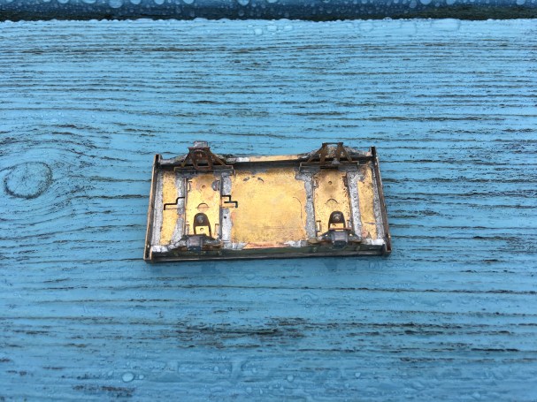
However, I did not spot the biggest problem until it was too late. There is an error with the design of the kit ends where one of them is missing the top gap between slats. The correct end is as per the right hand picture and had I have spotted this prior to the assembly of the ends, I would have been able to insert the additional gap with a piercing saw. Having missed the problem until after I had built the van, I decided not to sweat the parts apart to cut in the slat. It only shows to those that know it is wrong; the problem is that I am one of them so it does niggle!
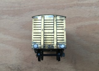
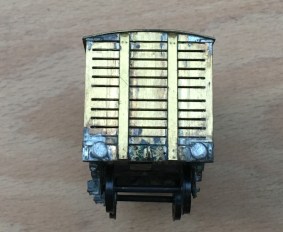
Contrary to the instructions, I did not loose lay the floors in place and instead created a cage arrangement by hanging the floors from rods that were secured to the roof. As can be seen below, this enables the roof and the floors to be released from the interior of the van. As with all my vans/coaches, this is secured in place with some bolts and nuts, so that the roof can be clamped tightly in place (I hate the cracks of doom that I see on otherwise fine models where roofs are not properly secured!). The detachable roof is necessary to both paint the vehicle but particularly populate it with the necessary sheep. You would be startled by how many sheep are required to fill one of these – around 50 and it costs a fair amount to populate each van. Thus, I have in mind casting some of my own in resin, although that is a story for another day.
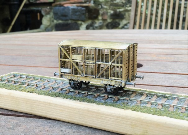
The problems with the kit did not finish with the problems noted to date. The iron strapping was not quite right, the springs for the axleboxes are too big and the brake lever/shoe seemed excessively skinny. Thus, these were all adjusted or replaced with alternatives. All this effort and problems to solve meant that the van took a great deal longer to finish than the week that I had available – so it has taken until now to photograph it. This is what it looks like and rather dainty and different I think it is too!
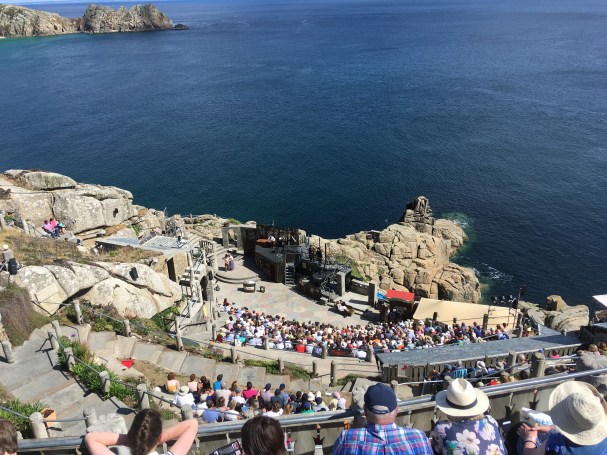
And what of the Minack Theatre? Well, for any that do not know it this theatre’s setting is simply breath-taking, being set in the cliff side only three miles short of Land’s End. As you can see, vertigo is an issue for visitors and all of the set, props and costumes had to be carried down to the stage level – exhausting work that took us three hours! One of other downsides of the theatre is that the seals, dolphins and basking sharks can sometimes be seen over the shoulders of the cast – which is distracting as you can imagine!
Only my wife was on stage, my duties including the stage building and front of house duties but with 7 public performances in five days, plus rehearsals there wasn’t that much time for modelling!

The musical being performed was Sweeney Todd – The Demon Barber of Fleet Street which follows the revenge that its namesake extracts on a corrupt judge and his beadle (with quite significant amounts of collateral!) for wrongly arranging for him to be transported. The most recent Hollywood version is pretty dark and definitely less watchable as a result – our version has just as death but with a great deal of humour too; especially as the leads had some pretty good comic timing to deliver it well.
The by-product of all these killings (ie bodies!) found its way into pies and one of the more jolly parts of the performance is where all the customers of these pies extol the virtues of their meaty dishes. So with apologies for my rather crude phone videoing; enjoy……………(I did, although strangely I had no taste for pasties whilst I was down in Cornwall!)………..

Another Wordless Wednesday……
…………again because I cannot put the words I would like to use on a public blog!
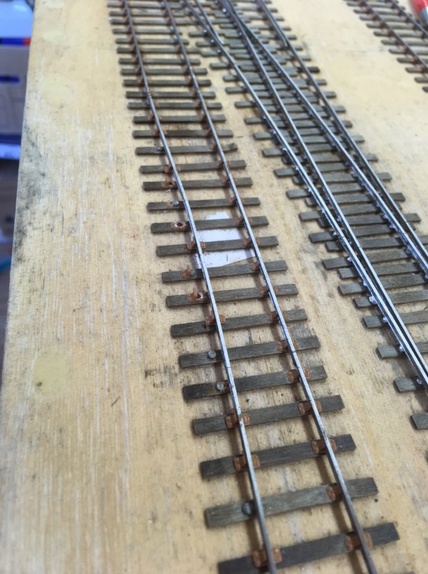
This was the scene that confronted me over the weekend when I was trying to fettle the layout for operation – a good number of broken chairs and detached solder joints. All this resulting in some fairly severe gauge narrowing!
It has been fairly warm here in blighty (I know that is a relative concept to some of the readers of this blog in the more far flung corners of the world – the Brits like to moan about our weather!). This has resulted in some thermal expansion and clearly I have not allowed enough joints to absorb this. It will be simple enough to fix, but altogether a pain.
Perhaps more irritatingly (because it has happened rather more), it has closed the gap on a number of crossings. This has resulted in a fair few short circuits and a campaign of dealing with these has taken a good chunk of my Sunday up!
The Glenmutchkin Pharmacy – Part 2; Beware Roofers!
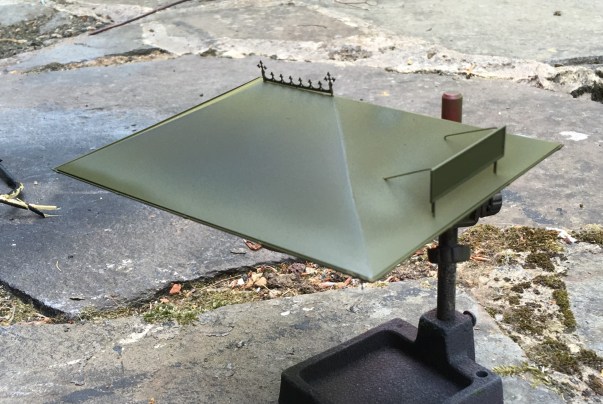
Progress with the Pharmacy building has continued and the roof is now nearing completion. I preferred using sheet metal (in this case nickle silver) for roofs as I find it is the easiest was to then include gutters. In this case, I designed the roof as a simple fold up etch and subsequently the gutters were formed by half round section from Eileen’s Emporium.
One of the pieces of artistic licence I went for relative to the real Kyle Pharmacy was to elongate the building slightly. This was partly because the prototype was a bit square and squat but also because I fancied including a decorative ridge piece. The Victorians and Edwardians did love a bit of decoration and this included the details to their buildings. There were numerous contemporary catalogues of architectural bits and pieces from which to choose from and I liked the idea of something pretty – especially given that this model will be right at the front of the layout. So I created a design of my own and etched it; along also with the characteristic sign that is so prominent in the photo in my last post.
Those that looked carefully at the prototype photograph in the last post will have noted that the roof slates were diamond shaped. These were, in fact, asbestos slates and were quite a common material for pre-fabricated and simple buildings such as the Kyle Pharmacy. Clearly they needed to be modelled but I did no fancy my chances of cutting the odd couple of thousand slates consistently. I toyed with getting some laser cut or cut on a silhouette machine but then had a brainwave – pinking shears.
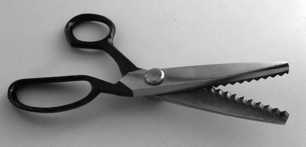
For reasons I don’t quite know, dressmakers use these to create zigzag cuts and even better, my wife had a set. However, she spotted me taking a look at them which meant I had a very firm talking too and was immediately banned from using them!! Researching them on the internet showed that they come in a variety of pitches but be warned not all of them have 90º serrations. I did find a set with a 4mm pitch which was a bit less than the 5mm that I thought was scale for the Kyle Pharmacy but as this equates to a 12 inch slate, I thought it was plausible and not a bodge too far. As you can see below, they produce a neat and consistent serration.
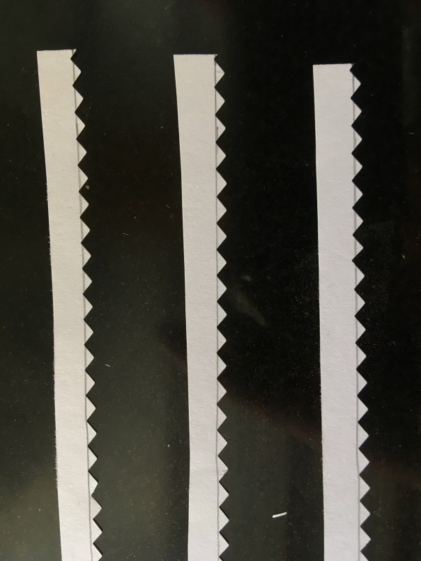
I cut the slates from plain paper in strips which I then sprayed a mid-grey colour because I felt that asbestos tiles might be a bit lighter than normal welsh slates. I deliberately allowed a tiny bit of inconsistency of colour to creep in, to provide a little texture to the roof. However, painting them was not easy as the air of the airbrush sent them flying – so I had to create a cradle to mount them in for spraying.
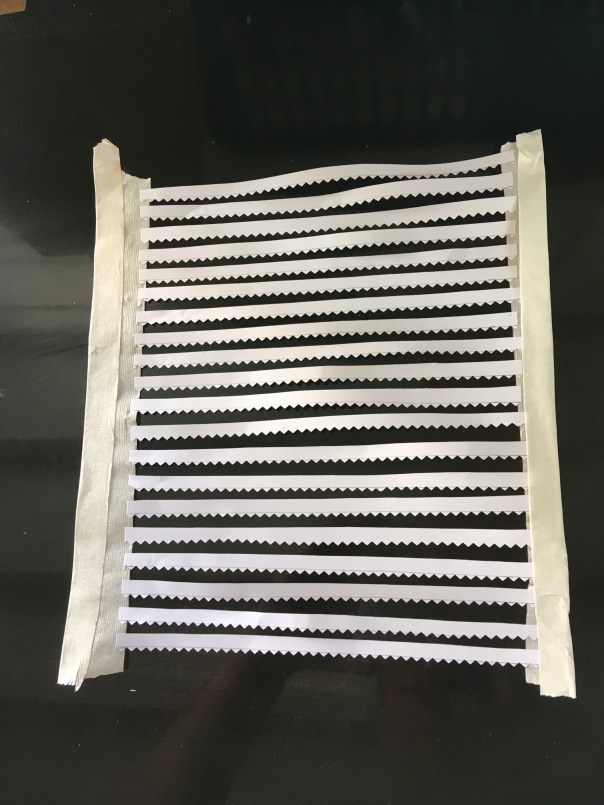
Once painted, I secured them with spraymount and carefully set them out, with the point of the diamond to the row above meeting the apex of the one below.
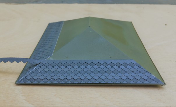
It takes some time (around 2 hours for a fairly small roof!) but I think the effect is quite convincing. I find the the best effect to make it look natural is to lay the slates as consistently as possible – you don’t achieve perfect consistency and these small imperfections end up making it that little bit more. Deliberately introducing inconsistencies tends to look a little contrived; including in this case my slightly differing shades, however, this was expected and can be overcome.
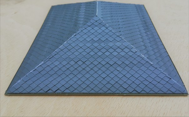
The blend the colours together, I washed the slates with artist’s acrylic always ensuring that the brush stroke was down the roof to mimic the flow of the weather.
I also formed the ridge and hip flashings with cigarette paper which I had first sprayed with grey primer and then secured with more spraymount. This was laid over 0.6mm brass rod to give the central lead roll effect – this was secured in place with superglue. I initially tried to make the lead flashings in sections so that the correct laps between one piece and the other was achieved but I never got close to a neat or believable finish. Thus I ended up doing this in one piece per run.
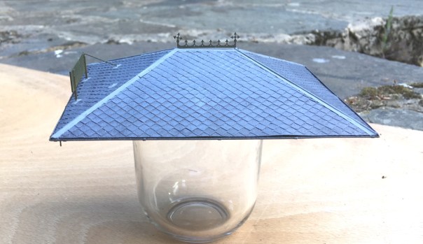
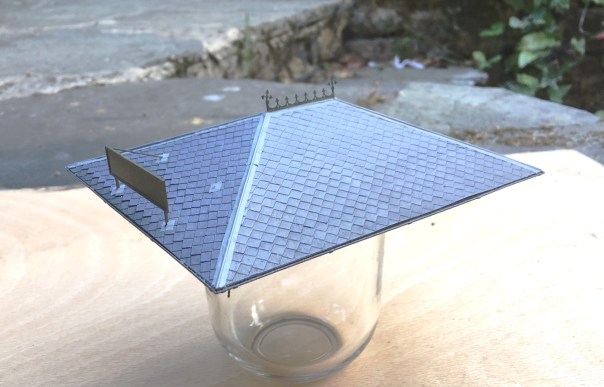
The front signboard will need some more work yet (partly because I have damaged it!), which will feature in a future post as I am going to have a bash at producing transfers.

The Glenmutchkin Pharmacy – Part 1 The Etchings
It is a fair time since I built my last building, so feeling that it was time that I rediscovered my mojo for architectural things I have made a crack at a building that will be a fairly key feature on Glenmutchkin – its pharmacy .
This is inspired, and largely a facsimile of, The Kyle Pharmacy that could be found on the approach to the ferry pier. Or at least it could until the 1970s when it was swept away to make a larger car holding pool for the ferry. In addition to being a characterful building, as you can see below, the real pharmacy at Kyle was a key part of the local community and I wanted to capture this feature in Glenmutchkin.
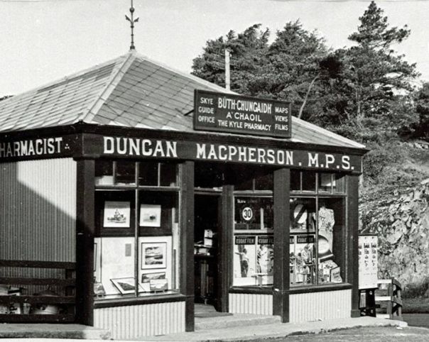
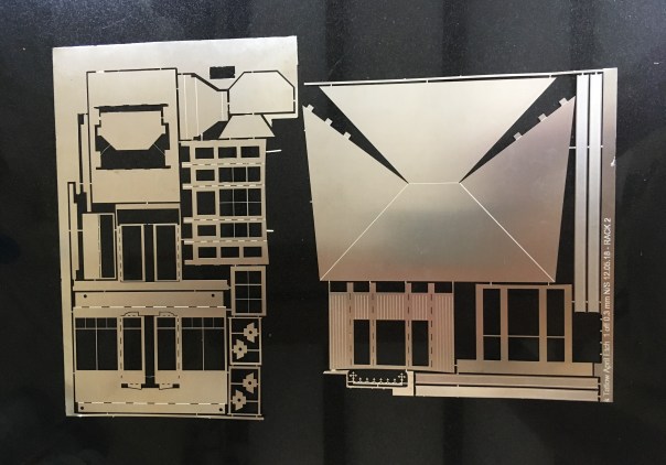
The pharmacy building is going to be located on the most prominent position at the front of the layout, so it definitely deserved some time being spent on it. Taking Peter Bond’s advice, it is going to be assembled in components which will make painting a great deal easier but rather than using plasticard throughout as he would have done, I have arranged to have the shop front and bay etched. I did so as I concluded that getting the slenderness and crispness of these was going to be key to get the feel of the model convincing. Peter is a professional architectural modeller and bending plasticard to his will is therefore his stock in trade – not quite so me!
So these are the basic etches back from PPD:
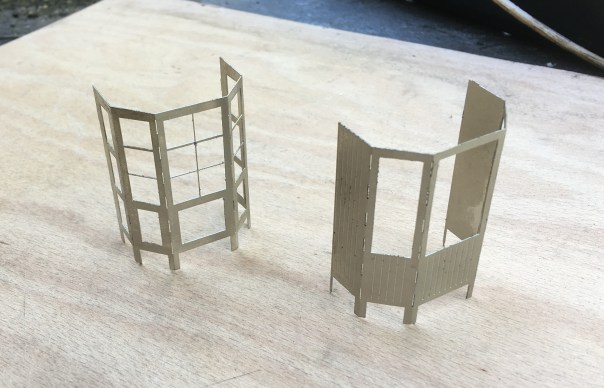
Some of the bay assemblies and the bay largely completed:
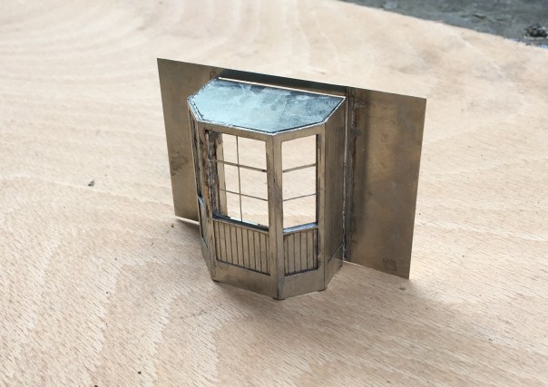
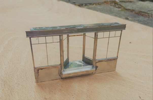
The real value of etching the components can be seen in the shopfront – I at least can’t get plasticard to look like this!

Clyde Bogie
The stock for Glenmutchkin has a recent addition and a rather beautiful one too.
This is a Clyde Bogie; the prototype being designed by David Jones and delivered in 1886. Initially this was a top link locomotive of the line but as time went past it was relegated to lesser duties. On Glenmutchkin it will be one of the locomotives for the branch passenger trains – equivalent to what the real locomotive did at the end of its live. This particular example was the last in service and lasted until 1930 and, as you can see, it picked up the LMS’s first livery of fully lined Crimson Lake.
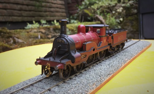
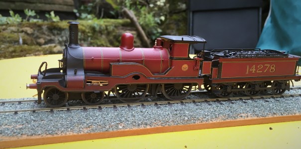
The model was built for me by John James from a Lochgorm Models etched kit. It is fair to say it was not an easy kit to master and John has cursed me a fair amount I believe for asking him to do this particular prototype…………… He would have cursed more if he also had to make the louvred chimney!
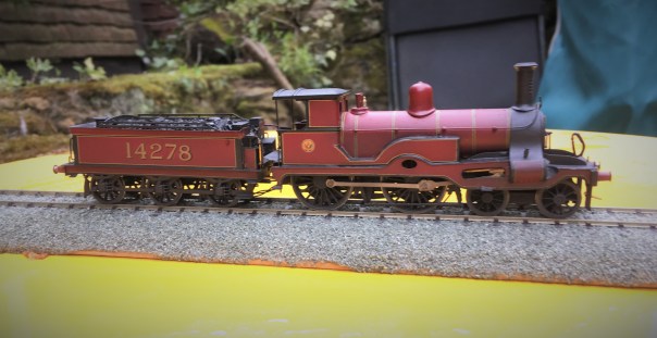
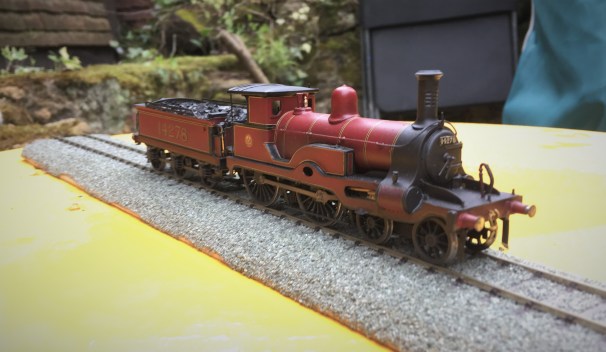
Since John has delivered it to me I have fitted a sound chip and some AJs. I need to fit some loco crew too before long. I suspect I am not going to find another sound fitted Clyde Bogie anytime soon as I have only ever seen one other built example so I can confidently say this is a first! I also seem to have disturbed the seating of the tender chassis as it is sitting rather low – a little task to attend to soon.
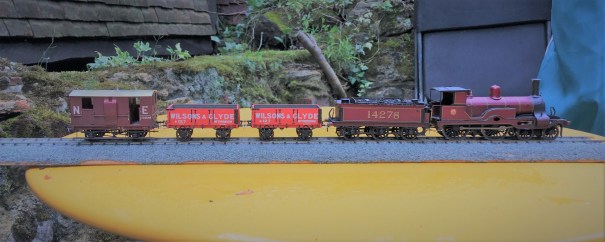
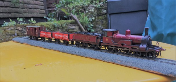
I have not been entirely idle whilst John has been busy and have been doing a number of little projects. Most of these will appear in future blogs but the pair of Wilsons & Clyde open wagons will not because this is effectively the same as the NB Jubilee Wagon I discussed previously. However, it is worth noting that Wilsons and Clyde were known to be one of the major providers of loco coal to the Highland so I am presuming these to be loco coal wagons.
And here is a picture of 14278 in action; albeit not at this point with sound fitted.

Dia 51 Test Build – Fox Heavyweight Bogies
After the painting disaster, I have been working on the latest version of the Fox Bogies. The prototype utilised a patented design with pressed steel plates to form the sides and ends which produced a stiff and resilient frame, better than the other contemporary options. Thus these bogies were very common amongst the pre-grouping companies with most of using them to at least some degree.
Although there are several model manufacturers that produce Fox bogies, there are no versions that use springing which I now prefer. As they were the primary form of bogie used by the Highland Railway, I need a few of them and thus I have been putting some effort into getting a top notch solution. In this regard, I have been assisted greatly by Justin Newitt if Rumney Models whose design of sprung bogie has formed the basis of this.
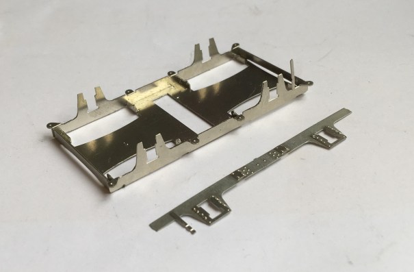
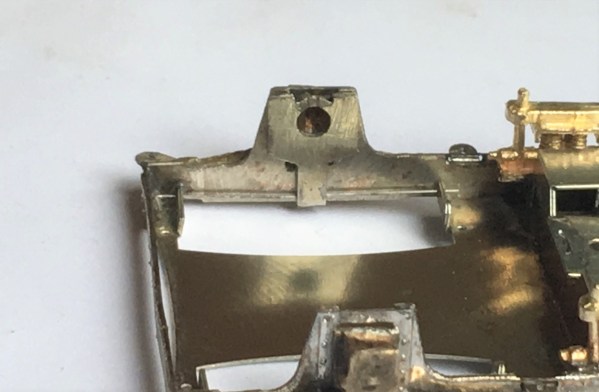
The model has primary suspension on the pin points based on guitar wire springs,
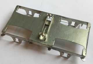
In addition to this, the design has a sprung bolster, also based on a guitar string suspension.

The castings I have used on these are from Lochgorm Models and the design has been conceived to enable these to be used either retaining their dampers (the cylindrical appendage at the end of the leaf springs) or with replacements that are a little more defined.
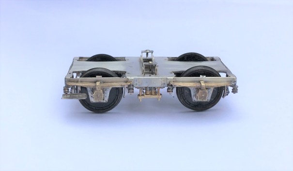
The etch is also designed to be provided with full stepboards as below or with only a short section to one end – as they typically were converted to during their life.
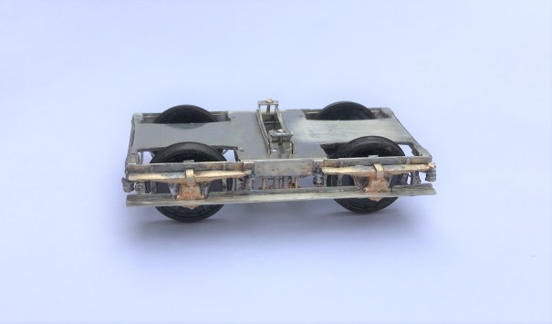
There is full brake gear provided, with a little trick where they do not pass under the axle (remember this view is upside down!) – this enables the wheel to be removed if this is required.
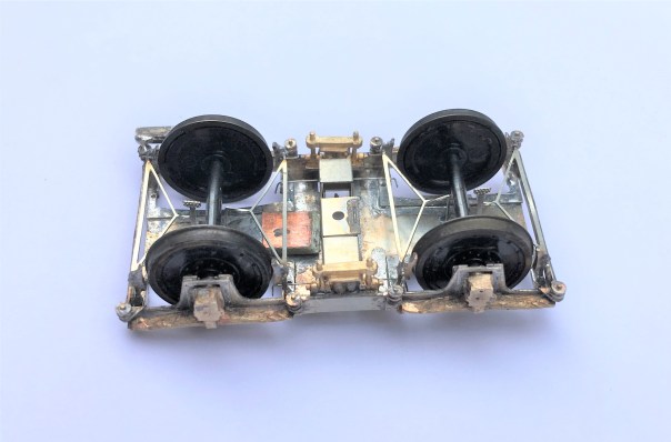
This is not the first version of these (don’t accuse me of not test building my designs!) and they are very close to done. The final change is to adjust the primary spring hangers slightly so that they are not visible when they are depressed (you can just see it poking above the sides in line with the axlebox), The advantage of computer drawn artwork is that things like this can be changed relatively easily.
These, and indeed the rest of the dia 51 full brake, will be made available for sale quite soon.
Previous parts to the test build can be found here:
- part 1 – the main body shell of the cupboard door version
- part 2 – the underframe
- part 3 – the second one, the sliding door version

Holland, no seriously……..
After Oly’s somewhat mischievous description of our trip to the Rail 2018 Modelspoor in Utrecht, I thought it might be worth taking a slightly more serious look at some of the layouts that will be unknown to most of the readers of this blog. Thus, even though there were some fine UK based layouts, I won’t include pictures of these as I am presuming more will be familiar with them (and if you are not, get out there and visit them at a show!).
First up was a model of Montherme station in N gauge. The real station is in the Ardennes and the railway really does come out of a tunnel, through a small station, across a river and back into another tunnel. The builders have used N gauge to its full effect, the hillsides rise up 3 feet (although this does make the layout excessively low) and it is very much a layout in a landscape which I like. It is based in northern France and the operators are very friendly, so if there are any brave show managers in the UK it could be realistically invited.


Regrettably I did not get the name of the following layout and ordinarily I don’t particularly like the steelworks/chemical works type of layouts as I find they are a bit contrived and consequently fake. However, I thought this one was a rather nice example and when you homed in on the detail, rather than let yourself get overwhelmed by the whole there were some really nice touches to it.


The next layout was a very fine rendition of a small Dutch village scene with a tram running through it. It was called Halt Tombroekstadt and whilst perhaps a little too neat, it was wonderfully modelled with lots of careful observations. It was automated and this could be worked on as the tram was either one or off!


Last up was my favourite – a layout called Pocahontas Mining Co built by a group from Dusseldorf. It was huge by most people’s standards and this enabled them to get full length coal trains on it without this looking silly – on occasions they had a double headed Norfolk & Western mallet with a similar banker at the back and that really was impressive to watch. You could imagine the houses in the foreground literally shaking on their foundations as a the whole train trundled by,


A few years back, I harboured desires to do something Canadian Pacific and regularly used to peruse Model Railroader. Pocahontas Mining reminded me of a number of the big basement layouts that so many Americans seemed to have – boy was I envious (indeed I still am!).
The layout had a number of great examples of modelling, just capturing the mundane and reminded me lots of O Winston Link’s photographs.

There were other very good layouts at the show but being one operator down and suffering from the tendency of my operators to either take the sit back form of management or engage any willing recipient into an in depth analysis of Scottish geography, there wasn’t time to photograph them all!
Wordless Wednesday – because I can’t publish my word…………
I am not one to fall behind trends (!!), so I am following the “wordless Wednesday” trend of many people’s blogs today.
However, my reason for not putting down many words is that the ones I would like to write ought not appear on a public blog.
Thus I will have to settle with “matting agent” and “where’s the paint stripper” as my words instead……….

The final installment of the test build sequence is a little further away than I had hoped!
Sliding Axles – A Reprise
Following my last post on sliding axles, I put the coach through its paces last weekend when Portchullin visited the Netherlands.
We I am pleased to say we did not have any bother with road holding it at all, even on Portchullin’s famously rubbish track – as long as you wait to the end of this clip you will see the proof of this. The axle has about 1mm play on the centre axle – 1/2mm either way – and this proved to be more than enough for the 4 foot curves on the layout. We did find it would be defeated by the rather tighter curves on Horselunges which was nearby but as these were down to around 2 feet radius, I don’t feel guilty!
The one issue I encountered was that as the axle slid over, the wheel rim would touch the side of the W iron and thus electrify it. This lead to some shorting issues if it came into contact with a vehicle of different polarity (I know it shouldn’t but well it seems to do for my stock!). Thus, for the next vehicle I will look to insert a layer of very thin copper clad paxolin below the W iron to isolate it.
So even with this issue I consider that the experiment to be a definite success and for relatively short bodied 6 wheeled coaches this will be my standard approach going forward. This suits the Jones shorter 6 wheeled vehicle of which Lochgorm and Microrail have examples. I think the jury is still out on longer 6 wheeled vehicles and a further experiment is going to he required as I am still a bit concerned there may not be enough side play.

