Category Archives: Glenmutchkin

Control Freak
I have been back onto the layout of late, with a view to get the first wheel turning on it before too long. That means attacking the electrickery things, beginning with the control panel.
I made a start on this by drawing up a diagrammatic representation in MS Paint and then using this to get one of the online firms (Vistaprint) to print me up a poster board to form the basis of the control panel. I am not sure I chose the right material as it turned up on a light weight foam board and I had to mount a sheet of aluminium behind for it to be stiff enough to be useable. But it did look pretty smart I thought………….
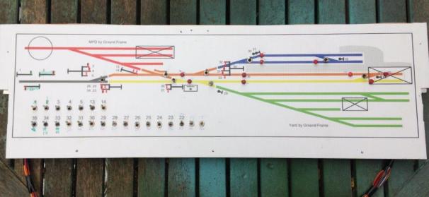
The control panel deals with all of the signals and turnouts that the cabin will have controlled, with local ground frames (which will be located on the boards locally) to be used to control the goods yard and the MPD. The latter will be arranged such that it can be located either to the front or the rear, to allow some flexibility in operation.
I have got to the point where the full extent of switches have been wired in and I am just completing the jumper leads. I took a lot of care to plan the wiring prior to any construction – despite the locos being DCC controlled, there are an awful lot of wires. This is because I have stuck with traditional control for the turnouts and signals. There is further complication as a result of the desire to incorporate some bells and even a block instruments (well maybe, at the moment it is just the wires!). So in all, there are 90 odd wires doing something or another on the layout.
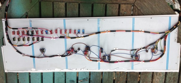
Somewhat in contrast to Portchullin, I have sought to keep the wiring as tidy as possible; everything is neatly collour coded and even labelled (to be fair it was labelled on Portchullin, but in a non colourfast ink………..!). I am hoping that this will make the wiring easier to debug at the start of the matter and repair if it does get damaged.
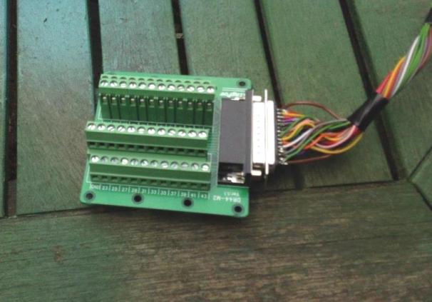
I am proposing to use a variety of connectors between boards and to the control panel, including this rather nifty varient of the D-sub range that is wired directly onot a cheeseblock wireless connector. Available to a variety of types from ebay including from this seller.

Going Long…….Part 1; the Underframe.
In comparison to the coaches that I use on Portchullin, most coaches from the 1920s (my chosen period for Glenmutchkin) are shorter and in many cases, even without considering the six wheeled vehicles, a lot shorter. This was driven by the technology and in particular the materials available to the railways of the time. There were exceptions though, and my present build is dealing with one of these – an East Coast Joint Stock 12 wheeler.
In the early 1890’s, the journey north was all about speed and culminated in the Railway Races to the North where the rival east and west coast companies competed to get their services to Aberdeen first. This came to an abrupt end in July 1896 when a west coast train took curves too fast at Preston and left the rails. Although the loss of life was relatively limited (for the time), excessive speed as a result of the desire to “speed to the north” was firmly blamed. As a result, the competing companies agreed no longer to race each other and instead sought to compete on the basis of the quality of their service and the luxury of their trains.

A GNR small altlantic hauling an ECJS express at the turn of the 19th Century made up predominantly of 12 wheeled stock
One product of this competition were some really fine 12 wheel coaches built for the East Cost Joint Stock Company (which was a joint company with the GNR, NER & NB contributing to the cost for trans-company trains). Built from 1896 onwards, these were several different lengths (this particular example was 66’11″) but all were long, seeking to use length and mass to iron out any track irregularity. To support this length of coach, six wheeled bogies were used, although these were rather infant in their design and used big transverse leaf springs as bolsters. In addition to being really characteristic and obvious – so they need to be modelled – I suspect they gave a somewhat bouncy ride!

Barry Fleming’s scratchbuilt body and part completed roof
I have been given a big headstart on this build by virtue of being given a nearly complete body/roof for a luggage composite (diagram 6 for those in the know). This was scratchbuilt by the late Barry Fleming in the 1980s and is a class bit of modelling! Barry gave it to my father, along with a couple of other coaches, to complete but as he has not managed to get this particular one, he has passed it to me to have a bash!

My etchings back from PPD
One of the reasons that this model was put to the back of the queue previously was that almost none of the parts required to complete it – in particular the bogies – were available, so it was all going to be a scratchbuild. As I was pouring over the drawings and pictures in the bible on things ECJS it dawned on me that the missing parts would be best dealt with as an etch and given my developing skills in etch designing, I might was well have a go. This is the product, an underframe, some cosmetic bogie sidesand some underframe details fresh back from the etchers.

The basic underframe has fold up solebars and buffer beams. Each of these also has integral fold over layers to laminate on the cosmetic exterior. This just about worked for the solbars but definitely did not for the buffer beams which distorted due to their thinness. I will make these seperate pieces next time, but might use folding jigs.

Coaches of this era tended to have four truss rods, each with a pair of queen posts. Stealing an idea from Alistair Wright’s designs, I made the queen posts up by a long etch that has a half etch length to wrap around the wire used for the tie rod. By folding this over the wire and then laminating the two parts together, a robust and simple post can be created. As it is two layers soldered together, it has the strength to allow it to be filed to a round shape to create the appearance of the original.

Although originally gas lit, by the time I will be modelling this vehicle it was electrically lit. Whilst I probably could have bought cast batter boxes, I decided to include them in the etch and very pleased I am too – they have come out much more crisp than any of the castings I have seen and were really easy to both draw and make. The remainder of the fittings seen here were bought in castings though, typically from Comet Models (now distributed by Wizard Models).


And this is where the underframe has presently progressed to.
I will describe the building of the bogies in the next installment, they are not for the faint-hearted!
Glenmutckin Shed Area
Glenmutchkin’s shed area is modelled on Kyle of Lochalsh’s (it is a mirror image) and I wanted to capture the typically cramped feel of the inspiration. This is the original OS map for the shed (ie old enough to be outside of copyright).
Key to this is the way that the whole complex centres around the turntable and the first turnout is almost tight against the turntable’s wall as this photo extract shows (notice there is not even a buffer stop on the far side of the well):
The first turnout is, you will see, a tandom and whilst it is not visible in this picture, almost certainly it was interlaced (as the Highland always seemed to always use interlaced turnouts). Well, interlacing gets quite crowded on a tandom turnout, as you can see:
It takes a long time to do all of the sleepers as there are a lot of them but once it is done, it does look rather impressive don’t you think?
_________________
Mark Tatlow
Testing Times with Terribly Troublesome Turntables
A decade or so ago, I did start a MPD type layout and got some way with the building of a working turntable but had lots of trouble with it and this did rather kill off my enthusiasm for the layout – with inevitable consequences…………
The difficulty was to get it to operate smoothly, with any level of reliability, and to stop with sufficient accuracy to enable P4 wheelsets to enter and leave the turntable without derailment. Well, Glenmutchkin needs a turntable, so it is time to confront that particular demon again – and he has not gone away in the meantime! However, I think I have put the blighter back in his box with the help of the Chatham Turntable Drive, a chunk of scratchbuilding and a dose more cussing………..
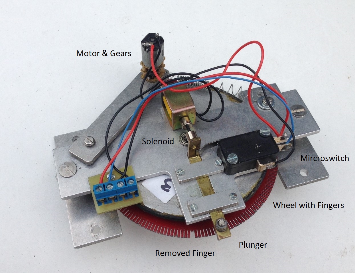
The Chatham turntable drive is named after its originator and is supplied in the UK by Model Railway Developments – not a great site listing I know, but there is a better Youtube video. The attraction of this particular drive was the mechanical locking arrangement – this means that it both stops consistently and then holds the turntable deck firmly there until activated again. The basis of the drive is a large wheel that has numerous fingers cut into it – the user then takes a finger away for the positions at which it is desired that the turntable will stop. When operated, a plunger runs across the tips of the fingers but where it encounters a gap, the plunger is pulled into the gap and cuts the power at the same time. To operate it again, the plunger is pushed free of the gap by way of a solenoid and the power to the drive reactivated.
The concept is great but there are some issues. The first was that the solenoid did not fully operate when activated. I found two problems with this; the first being that the control box seemed to send a less than full voltage to it. This was fairly easily dealt with by bypassing the control panel with the push button. The second problem related to the microswitch that alternates the power between the solenoid and the drive motor. The spring to this, even though it is quite light, was sufficent to offer to much resistance for the solenoid to overcome. I managed to overcome this by making sure that the rest of the plunger is as smooth as possible by rubbing all the parts down with fine wet and dry and a touch of oil. This takes a degree of care to set up to get the balance right and I am worried that it will be a source of problems for the future but for now it works.
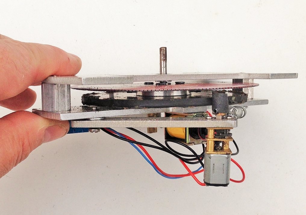
The next issue, is that the motor is not engaged to the drive wheel by a mechanical set of gears and instead has a brass wheel that runs on a rubber rim. This is probably designed as a safety feature to stop the motor burning out when a problem is encountered but it is prone to slipping rather too much. I have sought to overcome this by way of wrapping the motor wheel with sandpaper but this has only been partially successful. There are still more tweeks to do but I have found that it works rather better in one direction than the other, so this may be the ultimate solution!
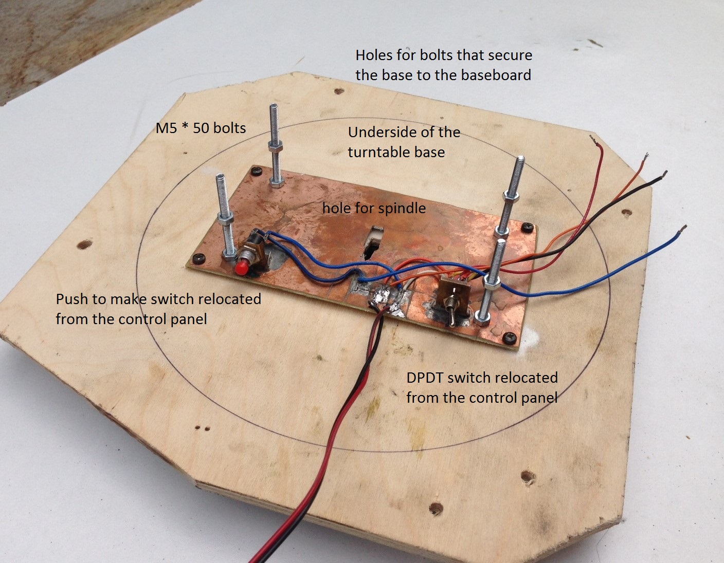
The next issue was to set the ride height of the turntable deck up correctly. I found that this had two aspects to worry about; the height of the deck relative to the rails that it runs on and then the height of the deck relative to the approach trackwork. I found that it is not sufficient to simply seek to try and get the deck set up correctly with fixed construction – it was simply too sensitive to minor errors. Therefore, I made up a mount with 50mm M4 bolts. By threading on a pair of nuts onto this, it was possible to adjust the exact positioning of the drive relative to the deck and then the entire assembly with the baseboard. The first of these nuts is shown on the above picture and once the drive unit is in place. the second set is tightened from above to hold it all in place. I am concerned, however, that they will loosen over time – so some “nut-tight” has been added to the shopping list!

I connected the shaft of the drive unit onto the turntable deck by way of a small piece of tube. This had grub screw clamps onto the drive unit shaft and a permenantly attached bolt on the top (bottom in the picture). The rod to the base of the turntable deck was reduced in diameter slightly such that it would rock just a touch and take up any inconsistancies in the turntable well. However, I ensured that the bolt was tight in both the rod and tube, so there was limited backlash.

Next up was a turntable well; which was another area where the gremlin made itself felt last time. Most of this had to do with trying to get the turntable deck to sit squarely and equally in the well. As already noted, I adopted the oppisite approach this time and built the well to fit the deck and simply relaid the rail afterwards so that it was exactly above the pivot – it has proved to be a whole lot easier and could have saved a lot of frustration last time!
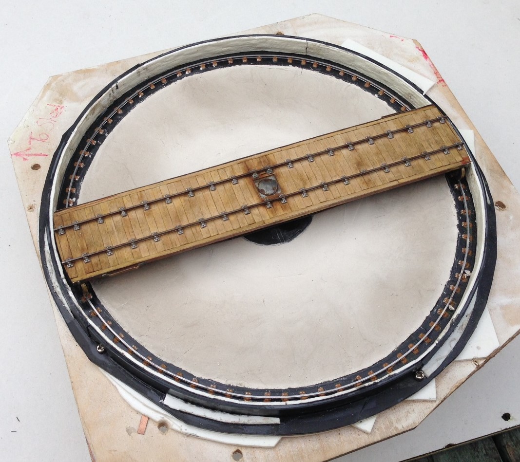
The well walls were formed of Will random stone sheet, as I did not think that they would have used anything particularly fancy on a turntable well. However, to stop them springing out of the curve, I laminated this with a chunky thickness of plasticard and also secured them to a plasticard base – this also formed the base for the rail, which is secured in turn with Exactoscale chairs. One thing I did notice when studying prototype photos is that the chairs on the turntable rail are quite closely spaced – presumably because a relatively limited number have to support the entire load of the engine (much less in number than in plain track due to the deck carrying the entire weight of the loco onto only four points). I have replicated this on my deck.
The dish to the well was, I have decided, merely ash ballast in the pre-group era (neat concrete was a much more recent approach), so I formed this with Das pressed into place and made as smoth as I could make it with fingers. This never gets crips and “machine made” so represents what I think it will have looked like.
I will look at the deck in the next post, after which hopefully it can be shown fully working and in situ! However, here is a peek:

….alliteration with thanks to Mrs Bennett; I really do remember Magistrate Maskew of Moonfleet Manor……..!
One for the Gorilla – tracklaying progress
Matters have been progressing with the layout on and off through the summer and a lot more of the track has now been laid. We have both the main line and the full run around loop complete, along with most of the bay and its run around loop too.
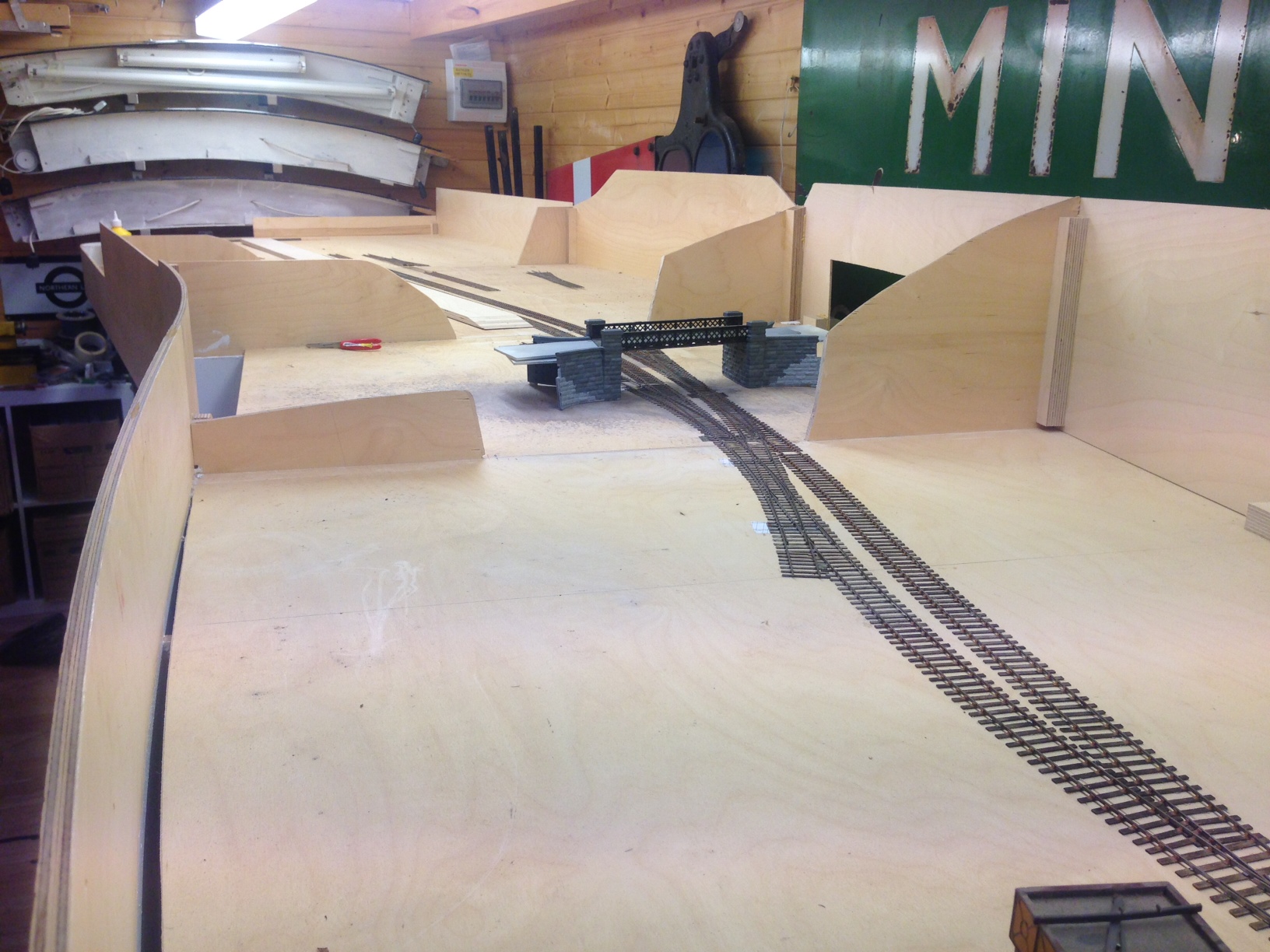
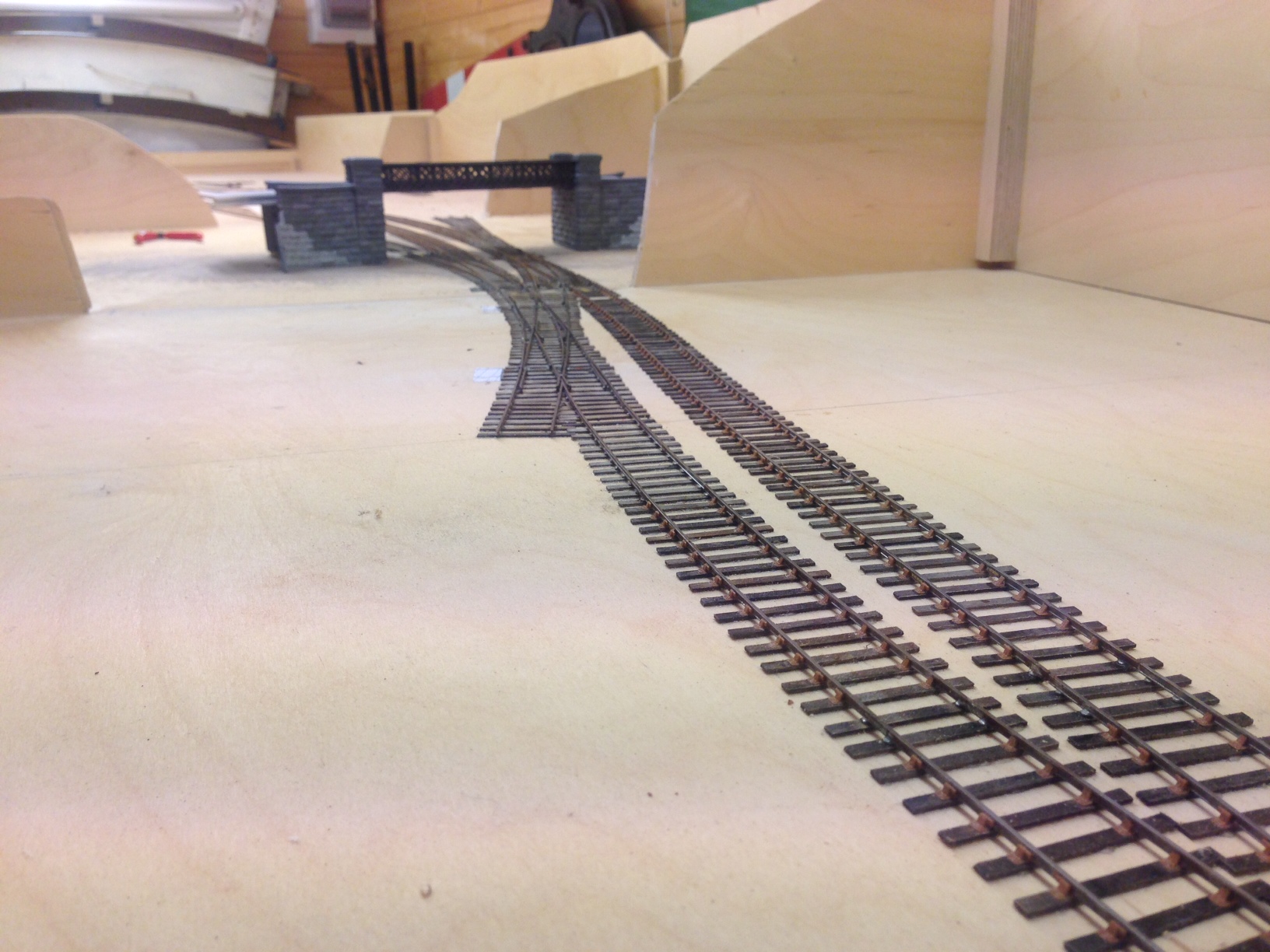
The line diverging in the foreground is going into the shed area, those visible below the bridge go to the bay (left) and yard (right). A signalling trackplan can be found here.
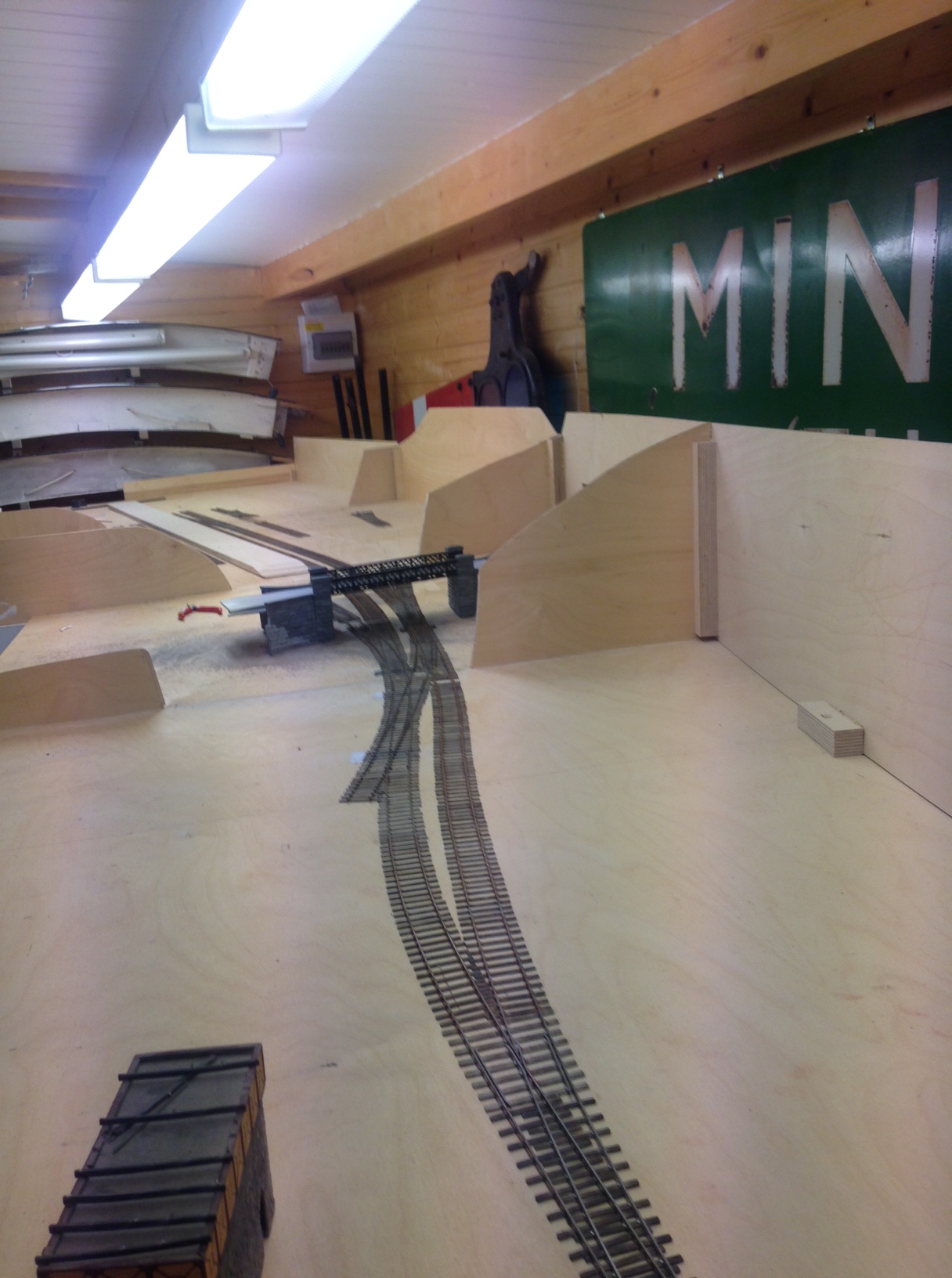
I quite like the sinuousness of the line, which can be seen here/ I have done this in order to give interest to the layoput but it is pretty typical (indeed characteristic) of the lines to the west coast as they wind through the mountainside. I do have in mind some hills to justify this in the finished item.
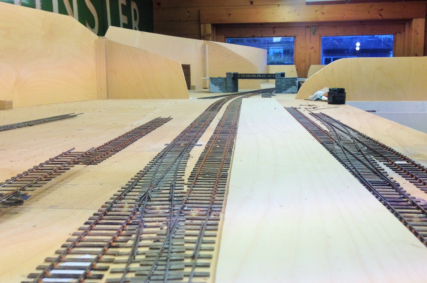
Already there is a sense of magnitude to the station forming, the platform face (which is not all in view in either of these views, comes in at about 7 feet – enough for an eight coach train of pre-grouping coaching stock. Really, its length is defined by the length of the bay – this will become clearer when the train shed appears because the bay has to start clear of this..
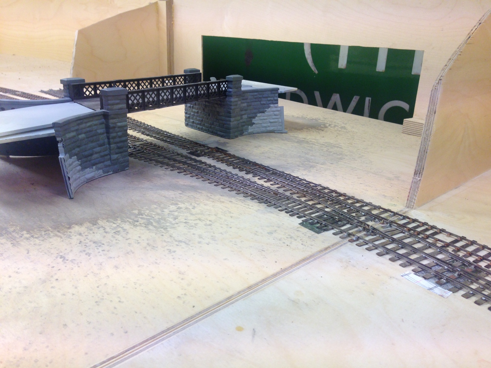
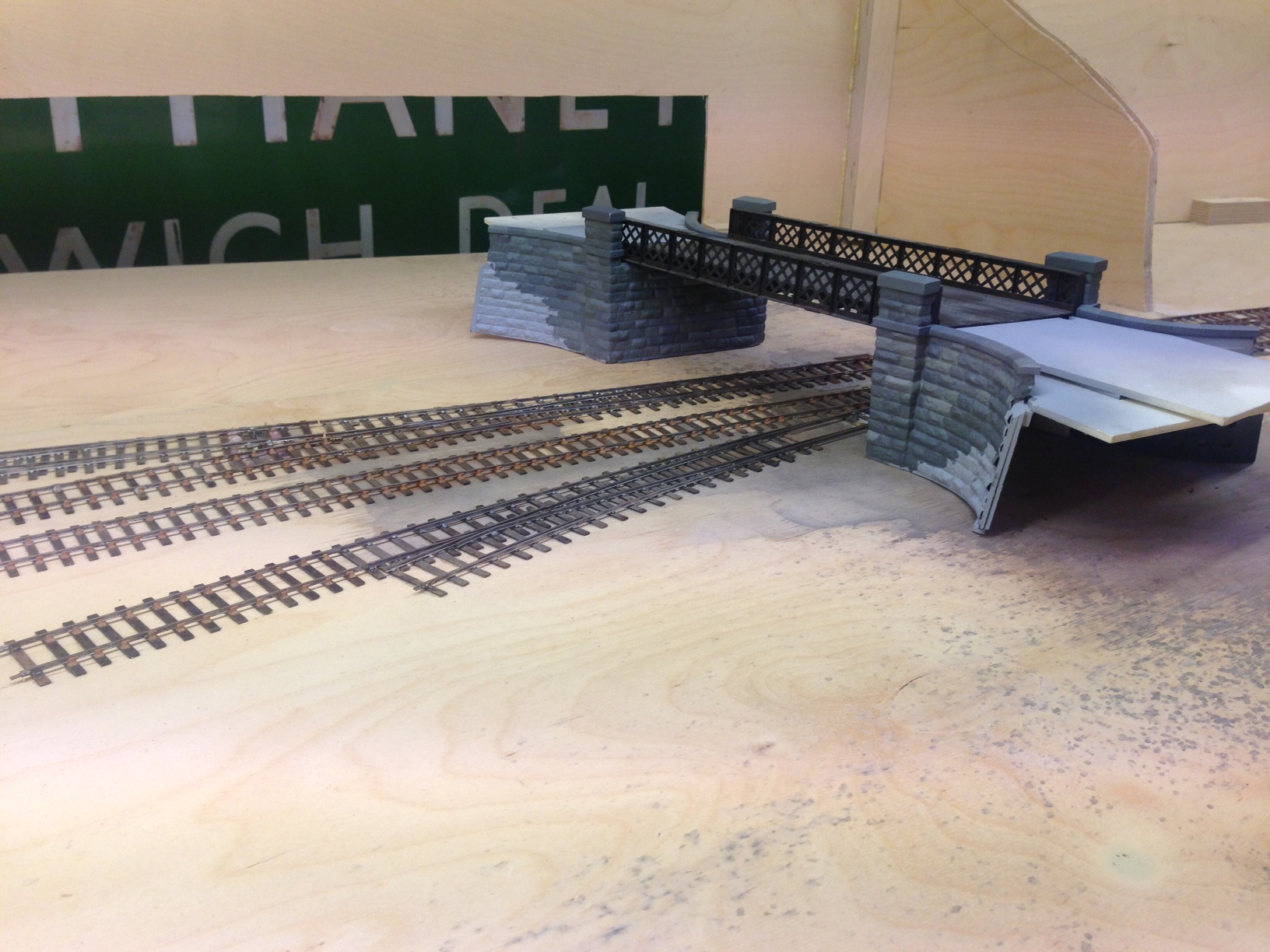
I have also placed into its approximate position the road overbridge that separates the shed from the main station area. The construction of this can be seen in postings here and here. The intention of hte bridge is to act as a scene blocker and thus to compel the watcher to view the layout from more than one location to appreciate it.
Tracklaying Commences
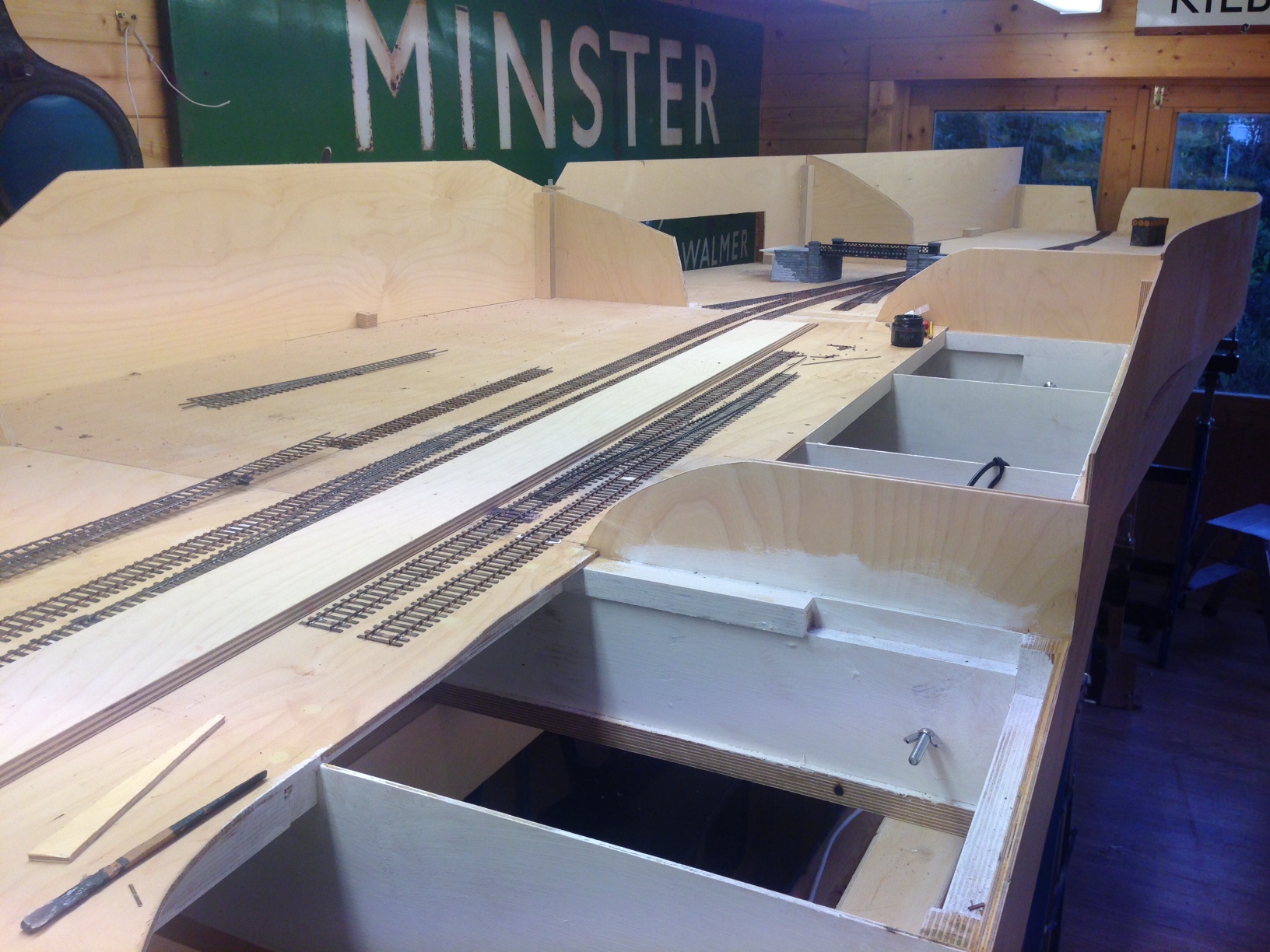
Definite progress was made with Glenmutchkin over the last 10 days, in that the first portions of trackwork have been laid. At last, it is an embryonic layout!
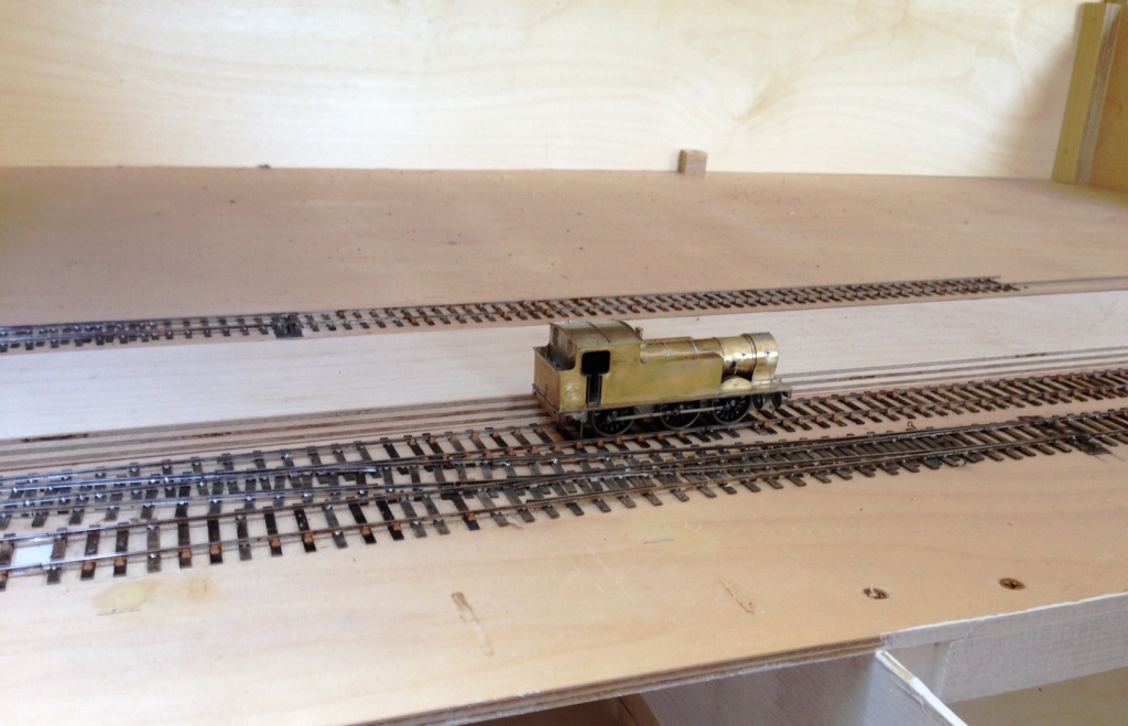
This was started at the two platform faces as in practise this is one of the major setting out points. This is because it is about the only straight bit of track on the layout and also because the platform needs to sit on top of the most substantial baseboard joint on the boards – where the front and back boards abut. The platform will be a separate element of construction and will bolt over the joint, hence hiding it from view.
The scrap tak is seen here sitting in the branch bay. The branch bay platform face is to its full length, the main line platform face still needs to continue for 500mm – into the trainshed which presently can only be imagined!
Now that the first few bits of track have been laid, a sense of scale starts to become apparent. Not for me the “model to the railway boundary only” approach – I am very definitely attempting to portray the railway in its setting.
The other major setting out point for the layout is the link into the engine shed; which is a single slip from the main line and a cross-over from the main run-around loop. The baseboard joint is mid-way through the crossover, so deines this end of the layout.

Boards Back Home
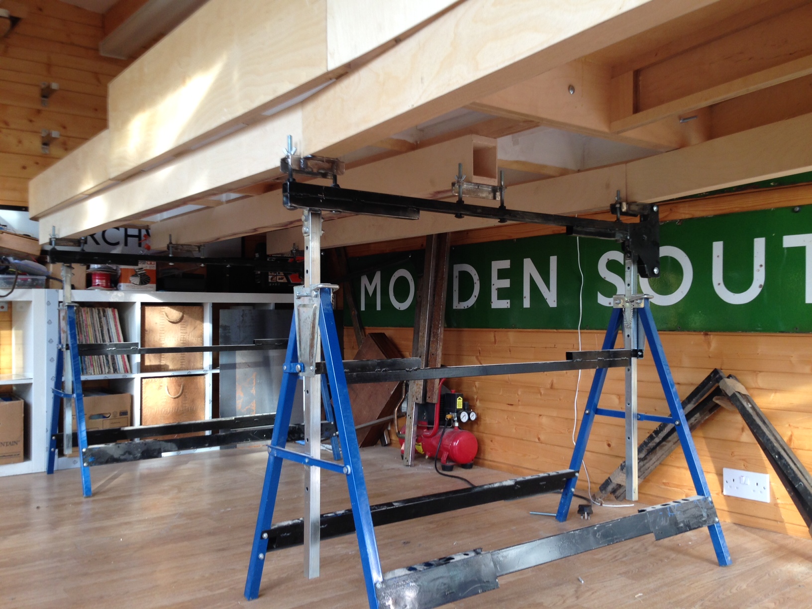
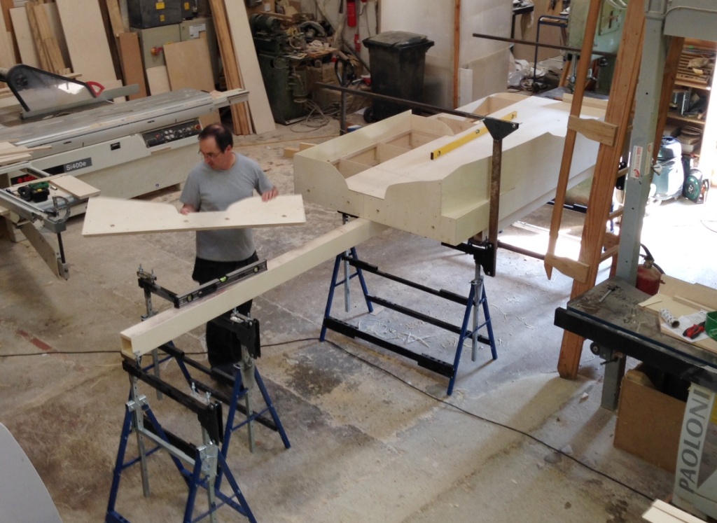
Just prior to Portchullin’s last two exhibitions, Tim of S&T Joinery brought around the last couple of boards so that all of the scenic boards are now back at home. Obviously, this meant that we had to do a test erection!
And very pleased I am too, especially with how flat they are. A rear contrast to the rolling hills affect that I managed on Portchullin. I am obviously hoping that this is going to result in much better and more reliable running.
The design of the leg and the supporting beams can now be seen more clearly. it does take a bit of time to get these level (caused I believe by the absence of levelness in S&T’s workshops! However, once the beams were level, it was a matter of moments to place the boards on them and connect them up. So I think we will do some setting out at the weekend.
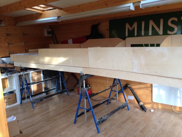
In some respects the photos don’t quite do justice to these boards and also how large they are collectively. The width in the top view is 1200mm and overall the length of the boards together is 5250mm. As will become apparent in future posts, I am going for the “railway in the landscape” feel and I don’t want it to fee cramped either.
And if anybody wants an electric loft ladder, this is where you go http://www.st-joinery.co.uk/
No Point Hanging Around
Whilst I have not put any posts up showing progress with the boards for Glenmutchkin, progress is being made and the last two boards are essentially now finished. I am hoping that with one more day’s work which will mostly be to build up a carrying box for the final two, they can all come home.
In anticipation of this, I have been building some turnouts and a bit of the basic trackwork.
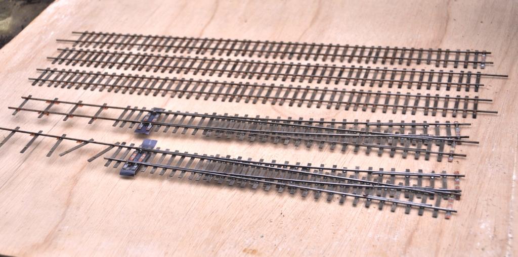
I am only able to do the turnouts which I am reasonably confident will not change shape when the track is finally laid out on the boards. In essence this means the crossings in the bay, the main line and the goods yard. I have also done one of the turnouts in the yard. So seven down, twelve to go including a slip!
I have also developed my approach to TOU’s slightly from Portchullin. As a finished article they look like this:
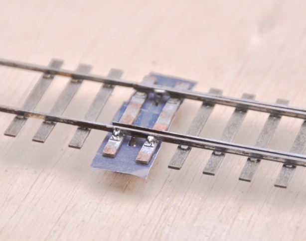
You will see that relatively little of the TOU is exposed (and when it is painted it blend away further). Equally it is much more durable than most of the other options out there because the switchblade is held by both a wire strip but also to some brass strip that is tight to the underside of both the switchrail and the switchblade. By installing this strip in this location, the switchblade is held in a vertical plane much better than other solutions. I think this leads to better running.
This is what it looks like as it is being assembled. You will see that in essence is it is merely a bit of copper clad below the switchblades, but lowered somewhat further due to the use of the brass strip. This allows the whole lot to be hidden below the boards.
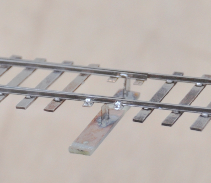
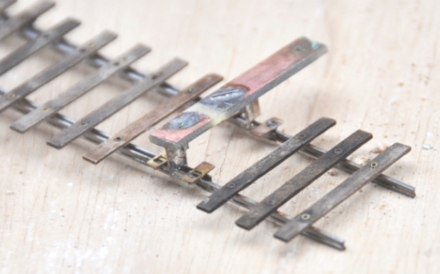
You will note the rather unusual arrangement of sleepers. This is called interlacing and was very common on many pre-grouping lines, including the Highland. I will expand on this in a future posting.
Christmas is the season for…………. jolly well finishing stuff off!
Over the break, I have been concentrating on trying to finish things. Like many people, I find it much easier to start a kit or project than it is to get it fully finished. Indeed, do we every truly finish our models – certainly not our layouts!
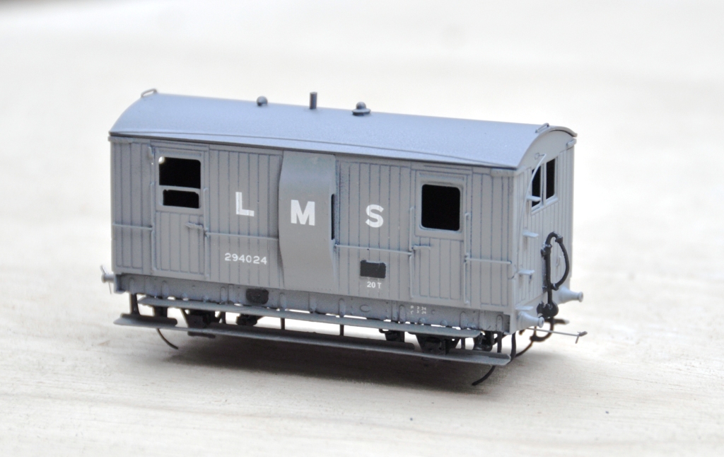
Back in March 2013, I completed a dia 39 goods break. These were the final Highland Railway break vans and it is not clear that they were actually finished prior to the end of the HR era. Given that I model in the mid 1920’s, I am quite content to do this in LMS grey which to date I have not seen the model depicted in! The main body painting has been completed and the van has been lettered but weathering, the interior and final detailing/glazing is still to be completed. Based on the Lochgorm Models kit with minimal adjustments (a few pipes below the chassis and sprung W irons in lieu of the compensation provided in the kit) this is what it presently looks like:
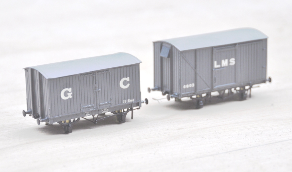
Also coming through the paint shops are a pair of vans. The first is a Great Central van build from a Mousa Models etched brass kit and the other is a LMS early standard van from an injection plastic moulded kit from Cambrian Models. Both are pretty simple models to build; the Mousa Models one was built as designed and no adjustments were found to be necessary. I only fitted springing to the Cambrian one and got rid of the rather too thick W irons in the process. Again the bulk of the painting is complete, but some dirtying work is definitely still required.
Apologies for the slightly squiffy photos; I left it a bit late in the day to take them and the light was poor. I have made a lot of progress painting the NER hoppers, but the photos of these really did not make it and need to be repeated. Something to post tomorrow I suspect!
First Four Boards Complete!
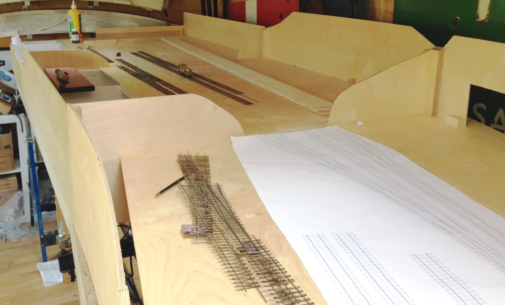
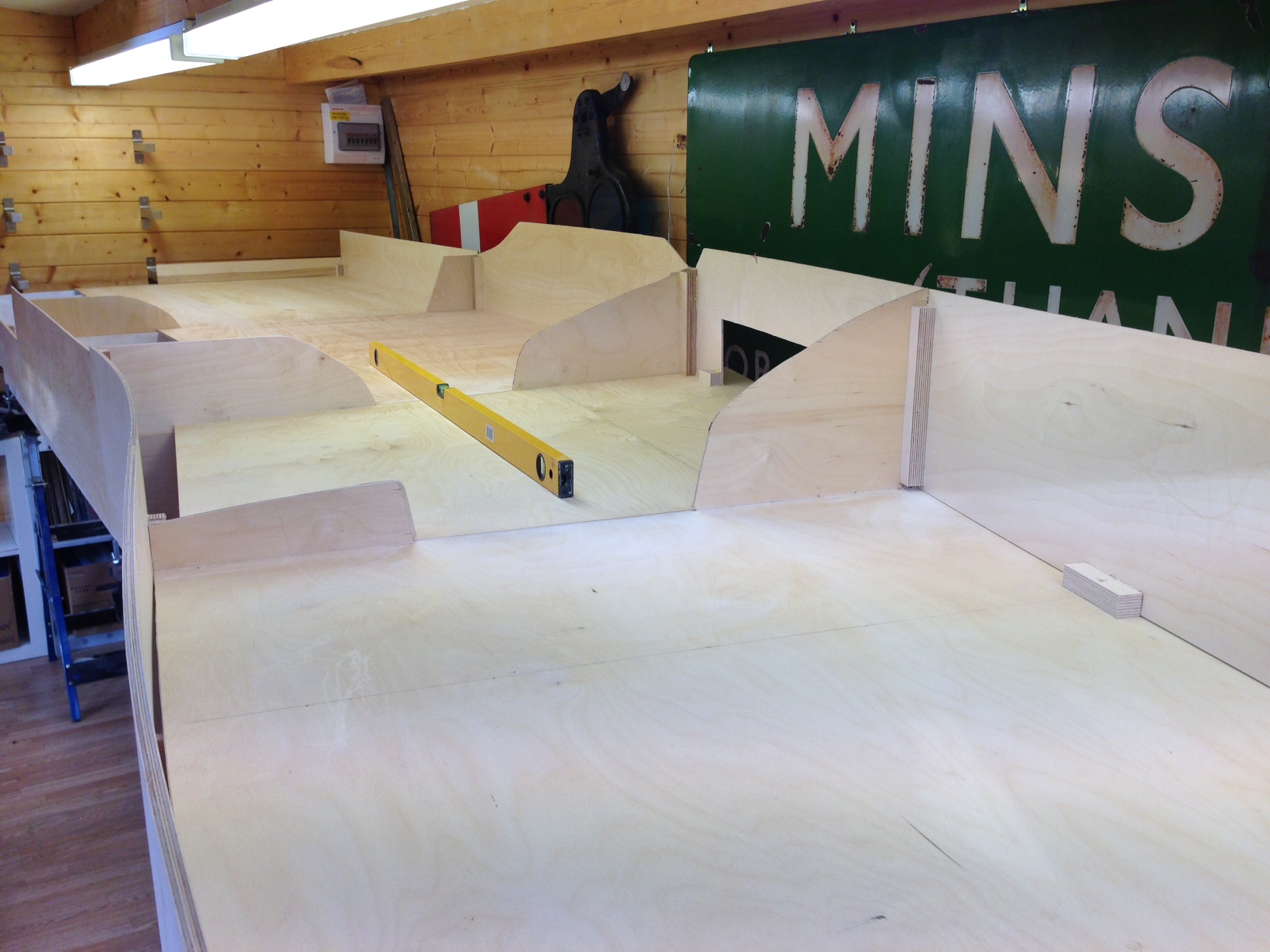
Julian and I have been putting a bit more time in on the baseboards, to the point where the first four are complete with the exception of their varnishing/painting.
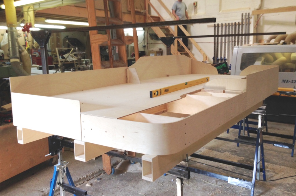
You will also see in the pictures that the beams that support the boards have also been completed. These span between the brackets that were shown here which in turn are supported by bolts that have been affixed to the builders trestles. This means that each point of contact can be adjusted for both overall level and also cant. The idea is that this is done prior to placing the boards on the beams, so that the whole thing can be levelled as one and the boards then just get plonked on. So long as the floor is not too wonky (like that in Tim & Julian’s place!), this does not take long and it is very idiot-proof assembling the layout perfectly each time.
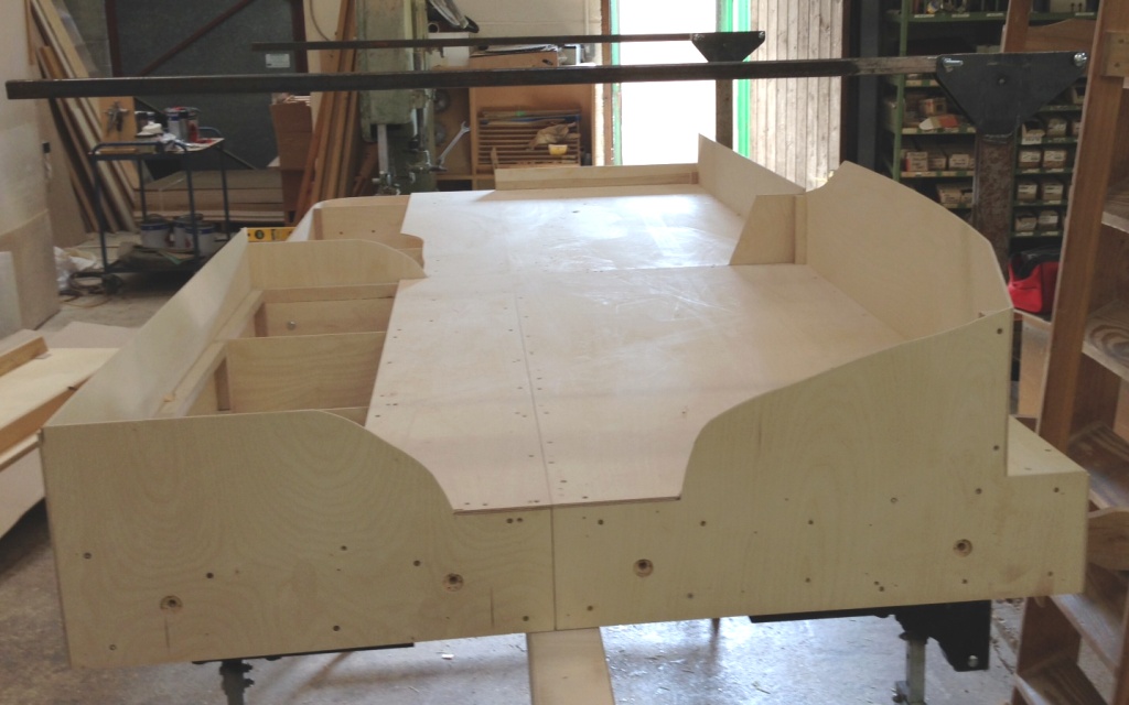
Also visible in the views are the gallows brackets that will support the lighting and facia. These are fairly meaty as they have to span over 1300mm from front to back, so the moment on them is quite high. What we have just found is that they are a tad low due to the beans being a bit higher than I had expected. A bit of adjustment will be required in due course; especially as the layout level is also a bit high.
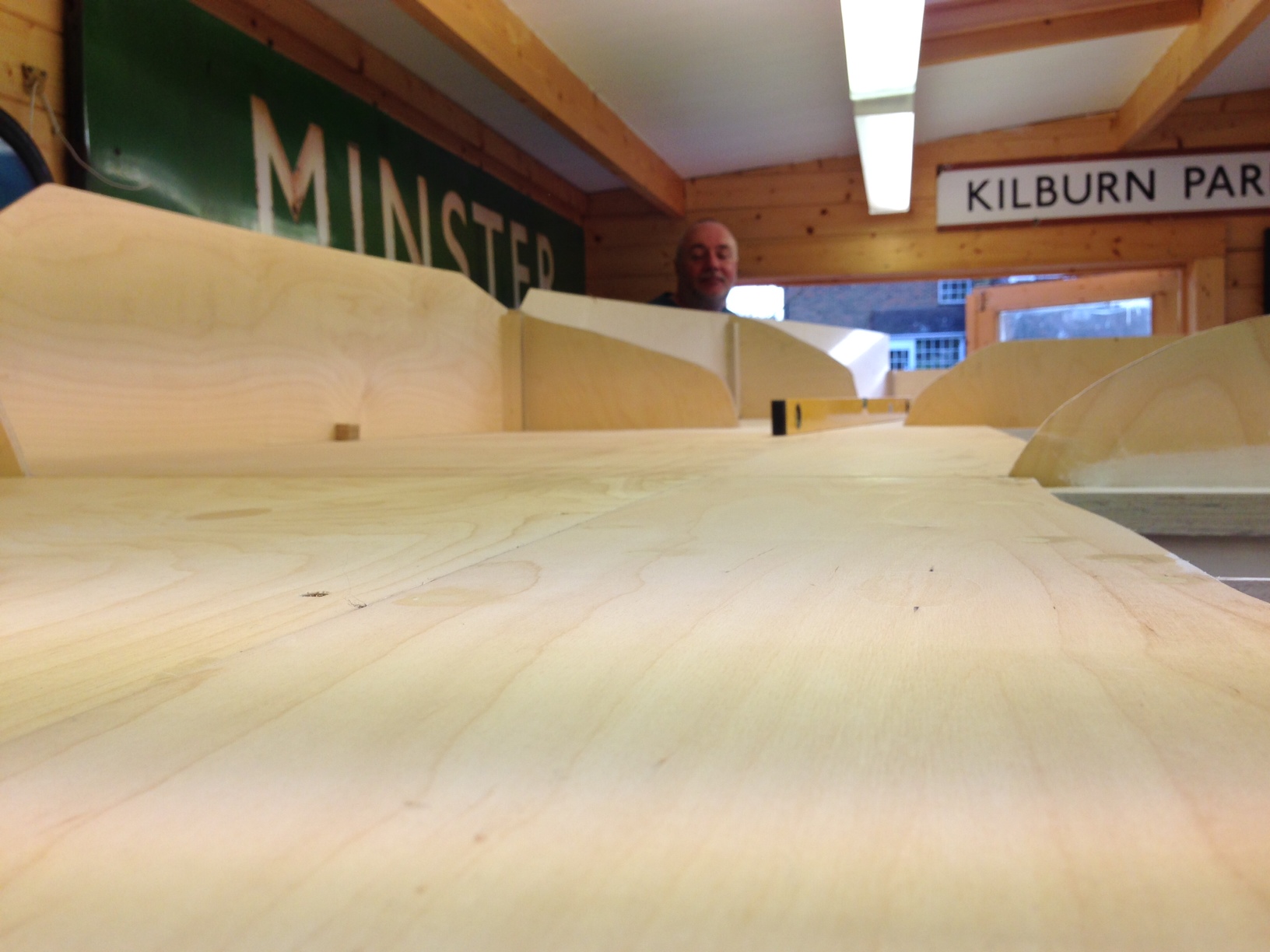
But the acid test of the new boards is shown in this view. On Portchullin one of the problems is that the boards rise up slightly at the joints – a problem I see a lot on layouts. This is dead flat; so we won’t see the trains doing any Casey Jones runs over the mountain ranges!
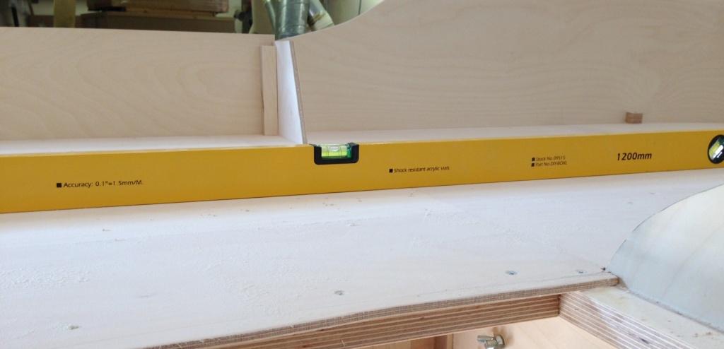
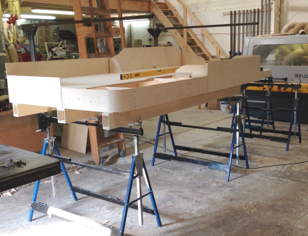
The next visit will get on with the last two boards, which will take up the rather obvious space where Julian is working. These will only be a single width in size as the boards are tapering in to 700mm wide at the end on the left in the view below. To give a sense of scale, the yellow spirit level is 1200mm and the dark one 750mm. (see Mr Ullyot – two spirit levels now………..)
So thanks again to Tim & Julian and if any of readers are looking at electric loft ladders; give them a call. S&T Joinery.
