Blog Archives

Something Fishy…….
Fish was an important traffic to the Highland Railway and as a result fish trucks were one of their most numerous classes of wagons. Given that Glenmutchkin is conceived to be on the coast, fish traffic will also be an important feature on the model too. There is to be a line to an off-scene harbour, so that I can justify a significant traffic. I already have a shortish train of fish vehicles, mostly open trucks, but I definitely need more
Back in April, I reviewed the Mousa Models LNWR covered van, which I was generally impressed with. Buoyed with this I spent portions of the last couple of weekends making a pair of the same manufacturer’s HR Drummond Fish Trucks. The kit is arranged for the variant that had a centre drop door, but there was an alternative variant with full length drop sides and at least some acquired morton brakes during their life. Thus, there are a few modifications that can be made if you wish.
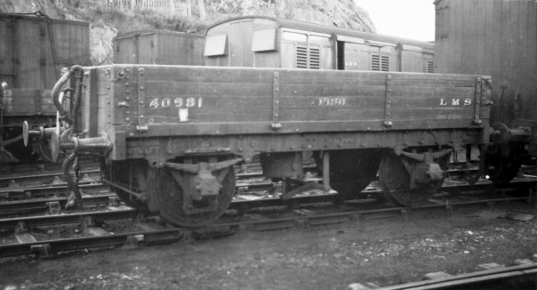
The above is a full drop side version of the fish truck at (I think) Kyle (AB McLeod, HRS Collection).
Having built a few Mousa Models kits and however regretful it is, I was not surprised to find there were no instructions included in the kit. This is a pain as there is enough going on with the model to justify some guidance and anyone who does not have my father’s book will struggle. Unfortunately, I did not take any mid way through photographs before I realised that some notes on its construction would be of assistance, but hopefully these notes and the pictures of the completed model will be helpful.
A first issue I discovered was that the resin casting was a touch distorted. The ends in particular bowed into the well of the wagon and the whole wagon had a slight twist to it. This is a common problem with resin kits but with care can easily be corrected. Put the body casting in hot water – as hot as you can tolerate with hands (so less than boiling – 40C is about right) and it softens sufficient to allow these to be corrected.
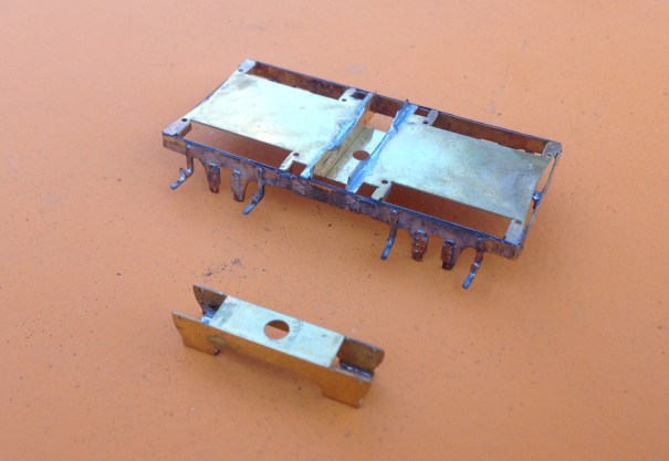
Although the resolution quality of the LNWR van was good, the quality of the prints that formed the masters for these resin castings was not nearly good enough. Significant portions of them looked as if they were sand castings and did not look real. The body sides were better and were capable of being improved to an acceptable standard with some work with wet and dry sand paper. The solebars were worse, possibly because they received less effort to tidy them up prior to being used as a master. I managed to tidy it up a bit more in the areas that were more free of rivet heads, but above the W irons this was not possible and will have to be masked with some weathering.
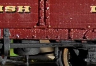
The roughness of the print is apparent to the solebar
The kit is conceived with sprung W-irons to Mousa Models normal design – details of the assembly of which can be found in my previous blog post. However, these need to be carefully lined up to the bolts on the outside of the solebars as the locating slots to the underside are oversized and allow too much slop. It is also necessary to use the Brassmasters axle spacing jig to ensure that the axles are parallel and correctly spaced.
As I noted previously, Mousa Models seem to wish to use resin parts for as much of their recent kits as possible. There were only a few parts where this was a problem on the LNWR van but the problem is rather worse on these fish trucks due to the additional elements of detail that they contain. Had some of the components been produced as etched parts, they would have been a lot more durable without compromising fidelity. I replaced the brake levers, coupling hooks, vacuum brake plunger and brake tie bars with etched components or wire but if I were doing any more of these, I would also swap the brake blocks/hangers because I have managed to damage two of these. Masokits do some that are suitable, although there may be others too that I do not know of.
Page 147 of the carriages and wagons book shows a drawing of how the Drummond patent brake levers operated. In this, it can be seen that there was a long lever running to the right hand end from the fulcrum of the “scotch brake”. This then met a smaller lever that operated in a cam arrangement on the long lever but also connected through a rod to the other side of the wagon. On this side, there was another short lever (so appeared on the left hand end on this side). In the kit, the brake lever is rather crude due to the need to beef it up so that it is durable but even then it is very vulnerable. Furthermore, there is a second long lever, which is not correct at all. Instead, I made up a rod from brass and utilised an etch from the Highland Railway Society.
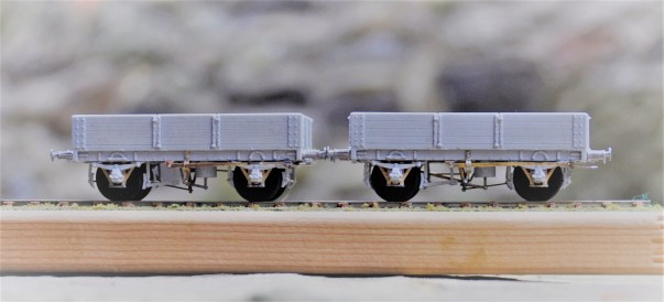
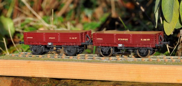
The principal side to the wagons, showing the missing brake lever now provided by way of a Highland Railway Society etching.
The patent braking system was, however, found to be unsafe because one side could be operated without the user on the other realising it (it cost someone some fingers, I believe) and the Board of Trade banned them for new construction. Therefore, many wagons had their braking arrangements changed, either by the use of full length levers and a ratchet or even a full change to morton brakes. I converted one of my wagons to the former by the use of some etched levers from 51L and an extra V hanger from the scrapbox.
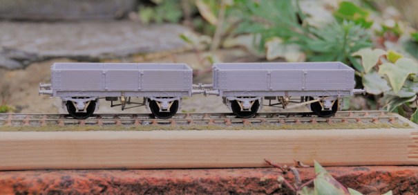
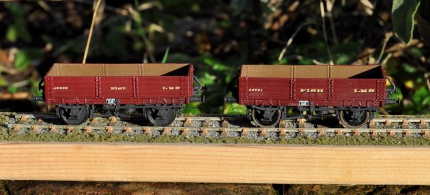
And now the subsidiary side to the wagons, showing the Drummond Patent Brake lever to the left hand vehicle and a replacement long lever on the right hand vehicle.
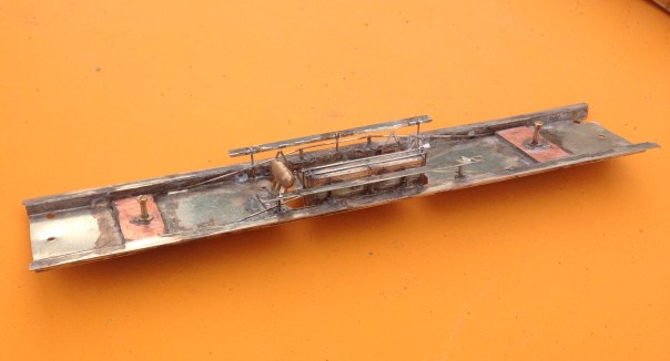
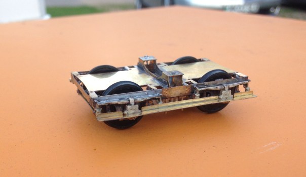
I also took the view that the buffers were too delicate to survive in use and therefore swapped them for Drummond buffers available from the Highland Railway Society. I also found it necessary to cram the whole of the underside of the chassis with lead, to get the wagon’s weight to a level that would operate the wagon’s springs.
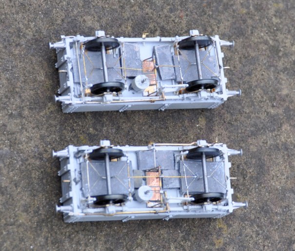
The underside – the rod to the Drummond brake is visible to the left hand end of the top vehicle.
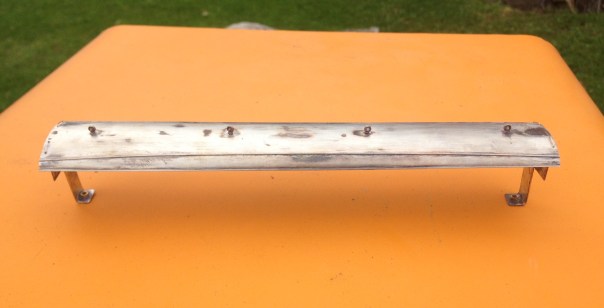
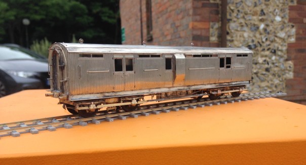
Although these will have been green with yellow lettering for much of their lives, I chose to do them in LMS crimson lake. Rather fine they look too! When carrying fish boxes, it is known that turfs were used to provide thermal insulation around the fish for the journey but my guess is that this was covered within tarpaulins. I have tended to find that the paper tarpulians (Smiths etc) are not that durable so I need to do some experimenting on alternatives – I do have something in mind. That will be for another post though!
Painted (well I seem to have missed the rims!) and awaiting weathering
All in all, these are quite attractive vehicles, very core to the required stock for Portchullin and the kits are a pretty good – but they could be better and easier to build if Mousa models had dealt with what are relatively obvious points.

Benfieldside at South Hants – Part 2
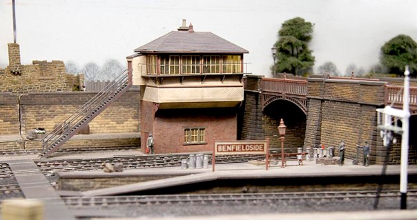
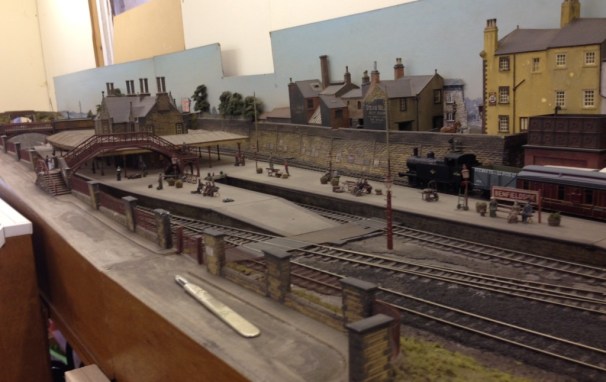
Following from last week’s post, here are a selection of further photographs from Benfieldside’s outing at the South Hants show, starting with a few around the platforms.
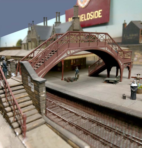
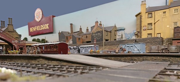

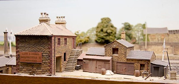
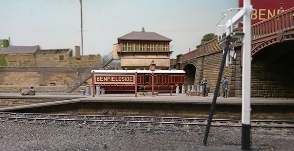
One of the charms of the layout are its buildings; typically constructed from cereal packets – good old fashioned modelling but very effective as you can see!
There remains a lot of stock to build for the layout and also a fair amount of restoration; the next bit of restoration can be seen in the picture below; a somewhat wonky signal (which will be rebuilt as a two doll to act as a starter signal for both the bay and the main loop). Hopefully, this will be done for ExpoEM, which is the layout’s next outing – see you there?
Many thanks to Dave Brandreth for the photographs in this post, along with some of those in its predecessor.

Benfieldside’s First Outing In a Long Time
Benfieldside has just completed its first outing for what is believed to be 17 years and whilst honesty dictates that we must admit to some glitches; especially first thing, on the whole it went really very well. As I have a fair number of photographs (some with thanks to David Brandreth), I will spread these over a pair of posts to keep people on tenterhooks!
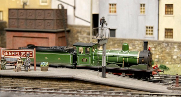
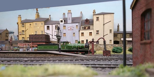
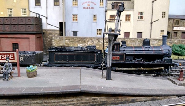
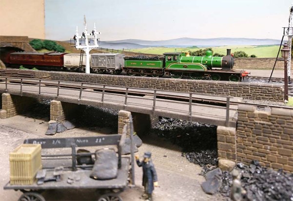
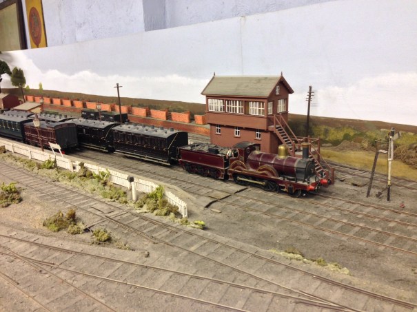
A NER C class (to become a LNER J21) pauses at the starter with a freight train.
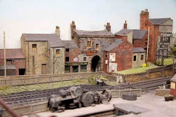
The same train in the distance, showing the goods yard with the station throat behind.
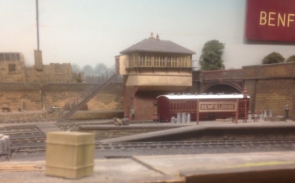
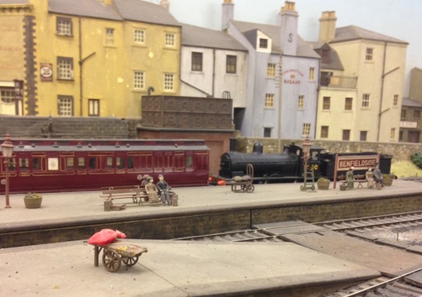
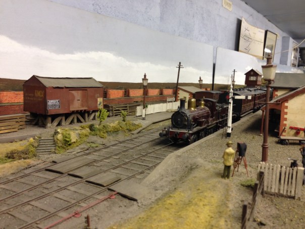
Things are quieter at the other end of the station where there is a full brake in the milk bay. The signalman has a commanding view; in part of the slightly droopy signal on the gallows signal!
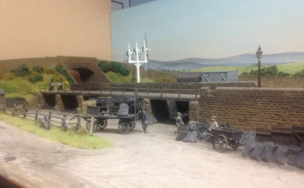
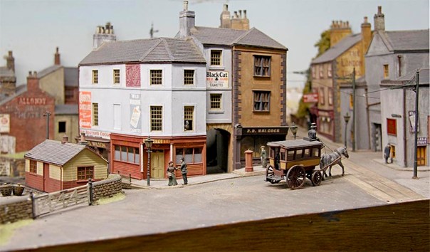
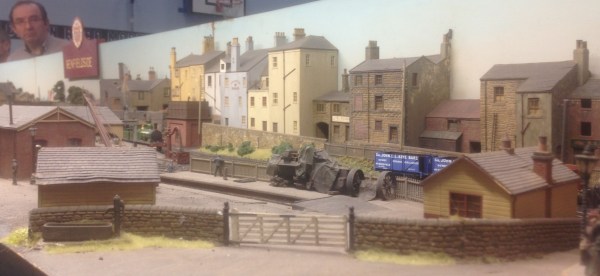
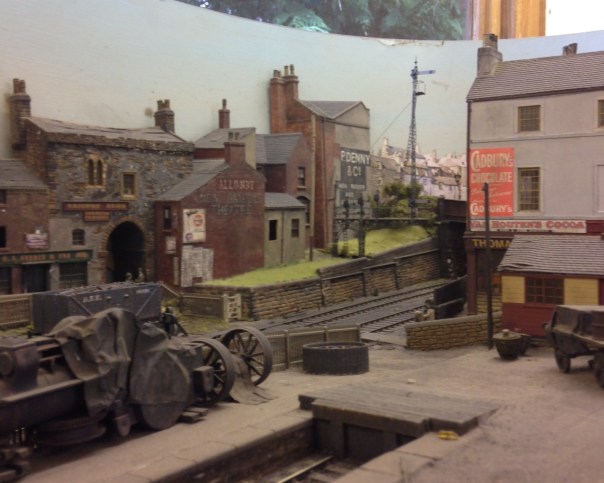
Because we were so pleased simply to having it running, there was no pretence to running a sensible service (and we were a little short of stock, particularly passenger stock). Thus, the poor coal merchant went without any delivery of coal all day! At least it looks as if he has enough to keep the coal fires of Benfieldside going for a little longer.
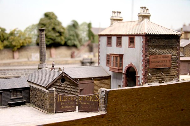
Next door, it seems like it might be lunch break at Iliffe & Stokes; builders, joiners and undertakers.
Moor to follow in a few days time…………… If you don’t already do so, you can subscribe to this blog by entering your email address in at the top left of the page. This means you will be sent an email each time I post anything on the blog.

South Hants Model Railway Show
In just over a week from now, I will be down in Portsmouth for the South Hants Model Railway Club’s annual show. Despite being a one day show, I find the show to be a good quality finescale show and the crew down there are very friendly, so it is definitely worth visiting. You can find details of the show here.
I will be assisting in the operation of Benfieldside, which I have illustrated on this blog in the past but it is worth looking at some of the pictures again:
I can assure you it is worth coming to the show to see this alone; and you might even find my latest construction effort – although probably still shiny like this. This is a D&S Models NER auto-carriage and really needs a sister to work with it but that will have to wait!
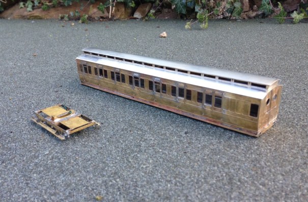
\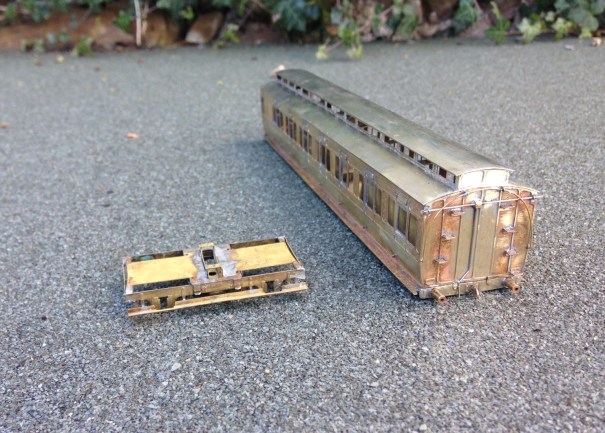
Stop by and say hello if you do visit.

Slip Ups – There is an Easier Way……………
My last post recounted the difficulties that I was encountering correctly wiring up a slip and the technique I had arrived at to overcome this, This precipitated various bits of advice including an alternative approach provided by Richard.
Richard’s solution is certainly a little easier than my approach to wire and does not need an additional point motor to run the extra switching required. It is, however, slightly less idiotproof in use than my version – this is because once the approach turnout is set for the branch in my version, the whole of the run was also set electrically. On Richard’s version, it is also necessary to decide whether the main line to yard is to be set for the yard.
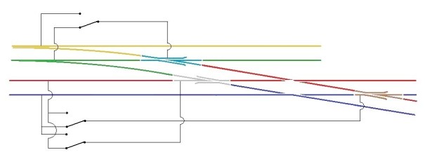
This is what it looks like as a wiring diagram and it is important to note that the approach turnout (A) is also operating one of the slip’s switches too.
I need to fire up the soldering iron now and undertake the correction, so that we can play with trains!

A Bit of a Slip Up…….
I have been continuing with the wiring of Glenmutchkin, but have hit a snag; one that I should have been ready for – the wiring of the slip, I had been aware that a diamond crossing was a challenge to wire and I was suckered into thinking that the switches on a slip could over come the challenge, Well I go that wrong…….!!
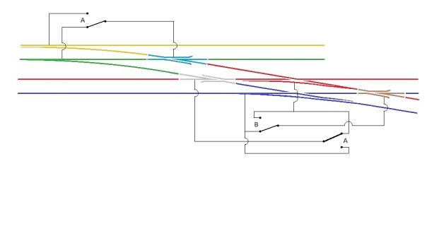
The basic problem is that there are a choice of two routes through a diamond crossing and each route requires the polarity of the crossings to be different. The diagram below, which shows how a diamond crossing needs to be wired, should illustrate the problem. The only solution to this is to power the crossing polarity by way of an approach turnout – if you really don’t have one to set the polarity with, then you are going to have to resort to some switches – but at least it will give you a good excuse to interlock the diamond crossing with some signals to remind you on which direction it is set!
Hopefully this is clear that the crossings on the diamond crossing are activated by detecting the direction of the switch on the approach turnout. If it is set for straight ahead, then a train can’t travel over the crossing and therefore the parallel line can so the polarity of the crossings are set accordingly. Conversely, when the approach turnout is set to the branch, the line across the diamond can be used and the polarity is set to suit.
The principal with the diamond crossing needs to be heeded when the crossing is replaced with a single slip as I have, but it does get more complicated because the switch of the slip can also lead to a different route through the crossings. The crossing to the left of the slip is the more straight forward as it is only activated by the approach turnout. However the right hand crossing is more complicated as if the approach turnout is set for the branch then it always needs to be in the red polarity whereas if the approach turnout is set for the main, then it then needs to be controlled by the slips switch.
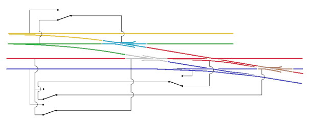
Hopefully the diagram above shows how this works.
The irritation I have, in addition to having wired it up wrong already (!) is that the approach turnout is on a different board to the slip. To reduce the number of wires crossing the boards, I have decided to simply use a duplicate point motor for the approach turnout located on the same board as the slip. It is expensive but rather more simple than the additional wires.
NB – please see also a follow up post on this wiring arrangement for an alternative approach.

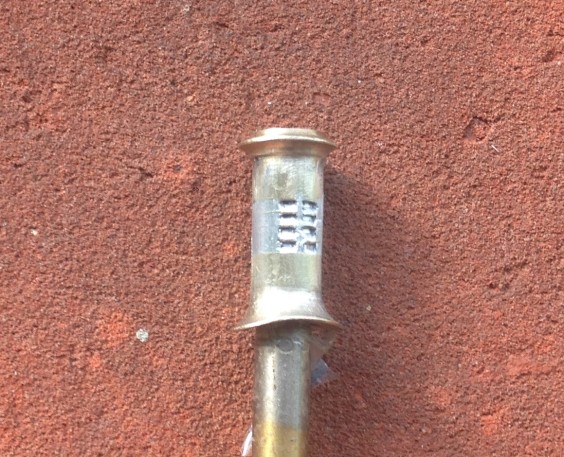
Making Louvered Chimneys
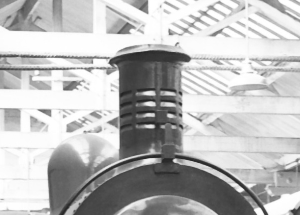
One of the most characteristic features of the Highland Railway’s locomotives for many years was the louvered chimney. This was fitted to almost all of David Jones’ locomotives and although some lost them over their lives, most retained them until withdrawal. Indeed this style of chimney can still be seen on the preserved Jones Goods which is presently in the Riverside Museum of Transport in Glasgow.
There is debate as to the reason that these chimneys were fitted but it is generally considered that they sought to assist in the drafting of the fire on the downhill sections of the line. There were many long descents on the line and regulator would be closed for such descents and thus the fire was not drafted by the exhaust from the cylinders. The louvres would have allowed the passing air to pull on the fire to keep .
Clearly for such a characteristic feature of the line, it is important to model it well on my locos but I am not totally happy with the renditions that are available. The whitemetal chimneys look too chunky and neither the cast brass (Lochgorm) or turned brass (Jidenco/Falcon Brass) have very distinct louvres. I feel that they can be improved and this is how I go about doing so; in this case starting with the Lochgorm Models cast brass chimney. Similarly, if you are turning your own chimney, the same situation arises,
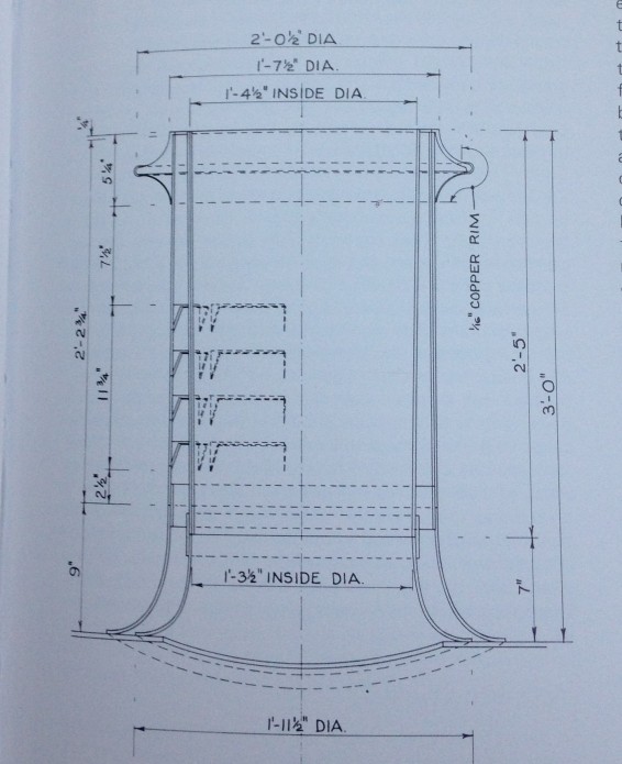
I started by some basic improvements to the chimney. I found that my casting was not parallel down the shaft of the chimney, being fatter at the top, and also not particularly smooth. I therefore turned it down a little on a drill with some needle files. The casting sprue was not particularly central so to be able to turn the chimney it was first necessary to file this to get it more central. Thereafter, I drilled out the chimney to 4.5mm diameter to its full depth on a pillar drill. I am doing this partly for appearance but really because I intend to put sound speakers in the smokebox and it is necessary to leave routes for the sound to escape – the most authentic being to chimney! Casting brass is very hard and this is no little task – it takes some time, lubricant and anyone in the house need to be able to tolerate a good amount of noise!
The Lochgorm Models cast chimney has a series of depressions to represent the louvres and these are what I felt needed improving. I started this with a piercing saw with a fine (OOOO) slot at the top of the cast depressions. This is cut across the whole width of the depressions and a little further beyond, ignoring where the pillars between the slots are.
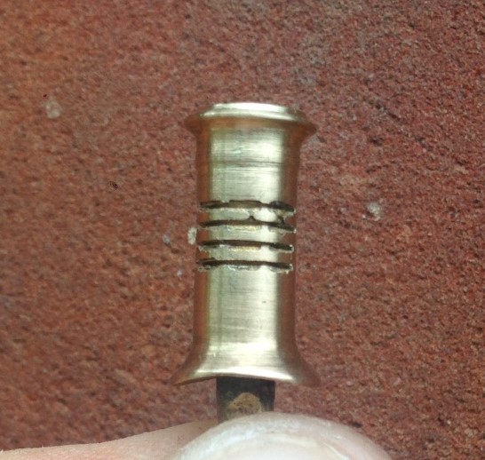
These are then given a chamfer slope with a needle file that has a blank face (to make sure it does not cut above the slot). This also needs to be taken beyond either end of the intended louvres to avoid the impact of any taper. The top three have been formed in the picture below, with the lowest still just the piercing saw cut.
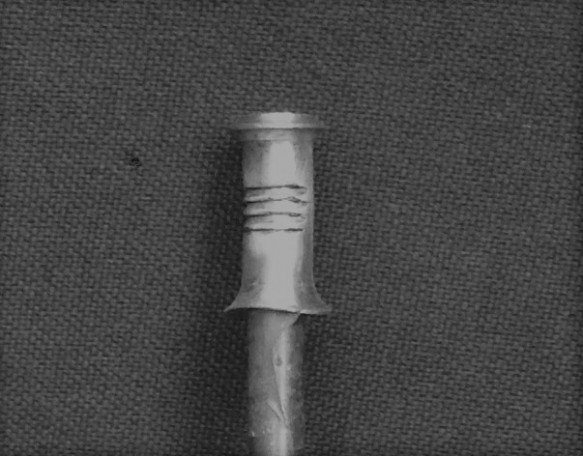
Once all have been formed, the next task is to undo all of the work by filling them in again! All of the gaps are flooded with solder. I used 145 solder as it would survive the reasonable temperatures that would be incurred in soldering it to the boiler but also be soft enough to carve out again.
The louvres were then marked out, starting with the two vertical rows either side of the central pillar that must match the highest point of the flare. Then with a knife, the solder infill between these is cut back out. The knife can cut through the solder to cut it out but does it will not affect the brass, so the louvre is reformed. I found that the technique was to initially cut it away and once a basic amount was removed the blade can be scraped side to side within the louvre to get a smooth surface. This brings up burrs of solder at either side of the louvre which are then cut out. This is what it looks like with the first two columns of louvres done – I found it best to do it like this as it was easier to get them vertical than by doing them in rows.
You will find that you get through a fair few blades doing this as the most challenging part is getting the corners crisp (and the photography is very cruel in this regard!). It is also easy to be a bit enthusiastic and accidentally cut pillar – if this happens, it can be reformed with a dab of solder and the process repeated until there is a neat row of four slots in four columns.
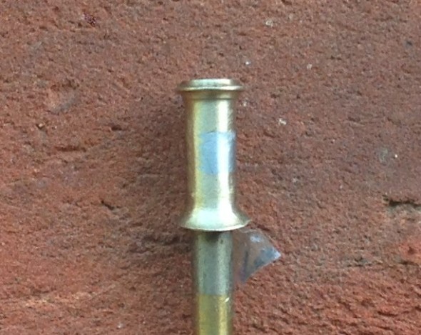
Once you are near to finished, a dusting of grey primer shows up any remaining inconsistencies and hopefully it looks something like this:.
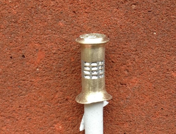
This process creates not only the slope of the louvre opening but also the dark shadow of the cavity. In my view these features are necessary to capture the feel of the distinctive feature of the Highland Railway. It takes around 2-3 hours to make each chimney and in I reckon it is worth the time and effort.

Dia 51 Test Build – Part 2: Nearly There
I no longer affix roofs firmly to the body of my coaches as makes both the building and the painting much easier. The downside of this is that there is the challenge of keeping the roof on tight without there being any visible joint between the two as this looks terrible. The solution I now use is to clamp this to the floor with 10BA bolts by way of brackets as can be seen in the photograph below.
As built, these coaches had full length step boards but they lost most of these through their life. They were electric fitted from the outset. The chassis below is close to finished except I have run out of vacuum cylinders so these will need to be added, along with the vacuum pipes.
The bogies are also a key part of the proposed kit and are something that I have been working on with Justin Newitt of Rumney Models – the idea being to combine the sprung bogie design that he has prepared with cosmetic etches for the sides and then the castings from Lochgorm Models or perhaps our own in due course. The bogie is quite sophisticated with both primary and secondary springing – the latter is on the bolster and is as below.
The primary springing is on the axleboxes and has bearing carriers, much like the Bill Bedford sprung W-irons. There are still some wrinkles to iron out so it is not there yet but they do make up into some pretty neat bogies; don’t you think?
The only area of the first test build that truly did not work was the corridor connections and it is going to be a case of back to the drawing board for these but other than the final few bits to be completed, the build is finished and I think the vehicle is handsome.
So, off to the paint shops soon, but there is a bit of a holiday to squeeze in first!
In Praise of Cellulose Paint
A few months ago I was criticised for preferring to use cellulose paint when I spray; the concern being that cellulose thinners are aggressive and will damage the air-brush.
On the basis that I am of the view that “if it works for me” then I am going to carry on using it I am doing so. I am helped by knowing that I am not alone in my preference as Ian Rathbone also recommends it and also because I have not yet had any issues with my airbrush.
The reason I prefer cellulose is that it gives an amazingly smooth paint finish every time, it drys very quick and gives a very durable finish. Judge the former at least for yourself.
More on the model in a future post……..

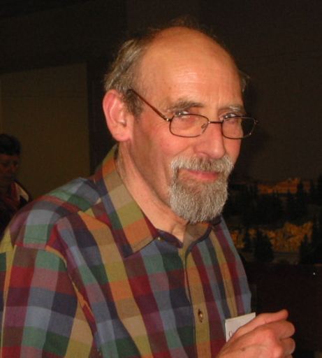
Richard Chown; 1941 – 2017
It is with great sadness that I advise that Richard Chown passed away last week.
Richard was a prolific modeller, typically of the somewhat unusual prototype and always in 7mm/1ft scale. Not for him a debate between BR blood & custard or blue grey, instead he modelled unusual and quirky prototypes from Norway, Ireland or France – that always made his models interesting!
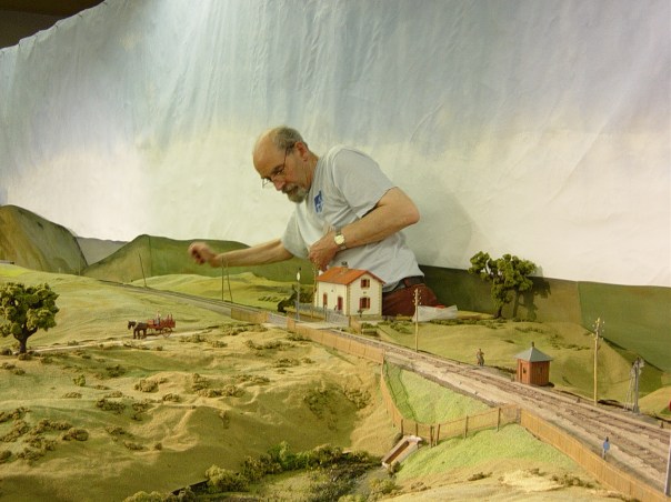
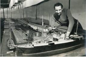
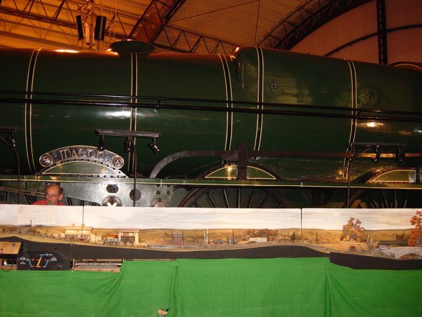
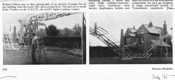
Although he did produce some smaller layouts, typically his layouts were somewhat on the large scale; tending from the substantial right up to a full size french viaduct where unless you were a basketball player you needed to stand on a box to reach rail height. This layout was Allendenac, which was based on a French line a touch to the north of Clemont Ferrand. The line was famous for the rather beautiful Rouzat Viaduct designed by Gustave Eiffel as a sort of trial run for the Eiffel Tower.
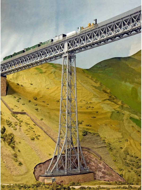
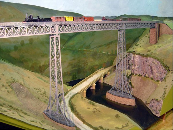
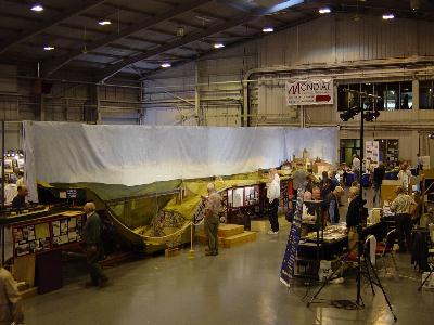
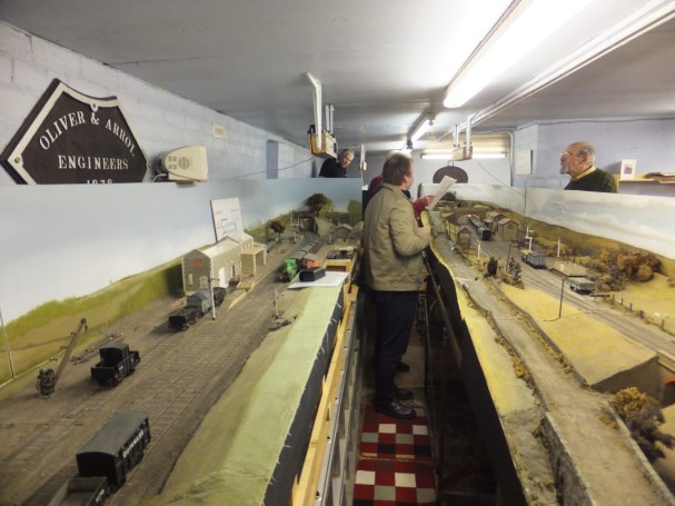
All being made in 7mm/1ft made for a somewhat large layout and to give a sense of its scale, in the picture below, all but the person directly in front of the viaduct is standing on a box and in the view below that, you can see Richard at the rear someway up a ladder and still not to the full height of the layout (so you see Mrs T, I am not that bad really………..).
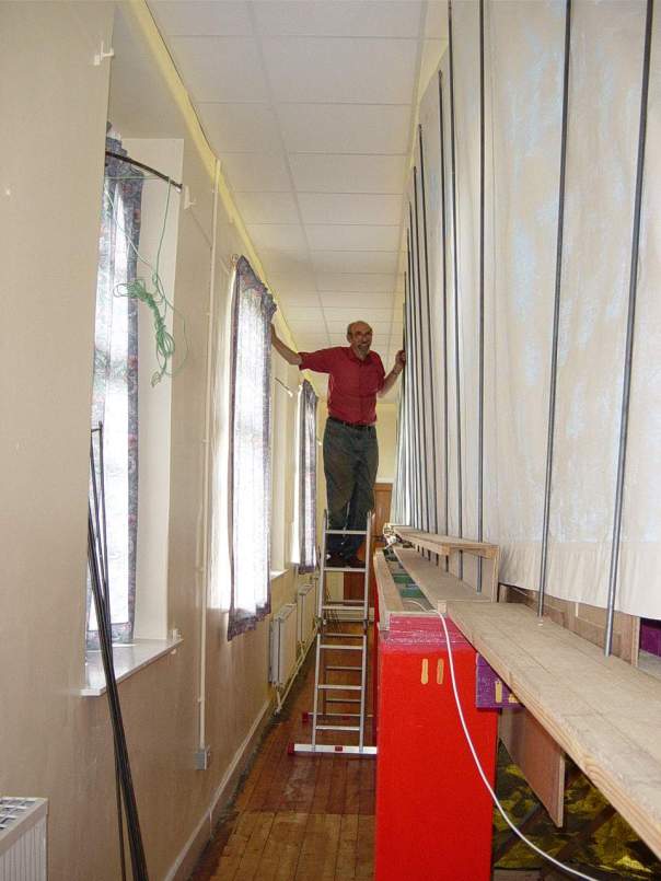
With a layout of this size, access points to maintain (or build) the layout are important and here is Richard popping out of just such a hatch!
Just because the layout was big does not detract from how good the modelling was, as these pictures show.
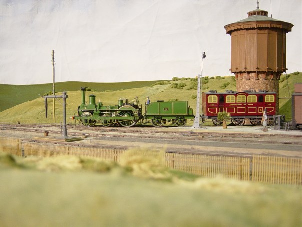
Naturally, as he modelled the esoteric Richard had to scratch build everything for his layouts and he was a very talented modeller as you can see ……..
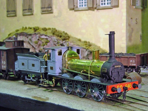
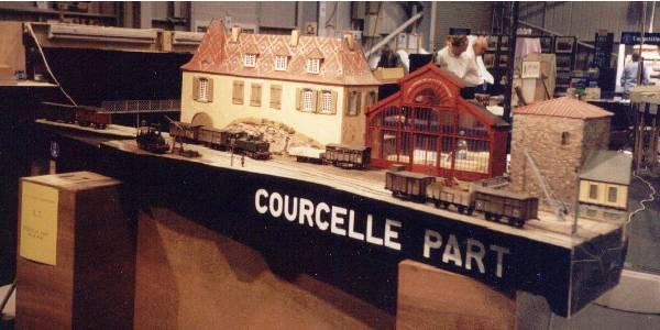
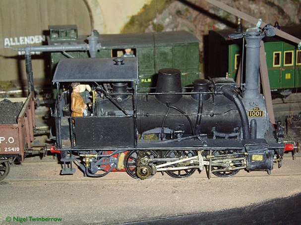
This locomotive operated on one of Richard’s smaller layouts, Courcelle Part which was built for a Gauge O Guild layout competition. It used some of the buildings from Allendenac and also its stock to create a more portable exhibition layout. As I understand it, Courcelle Part had some cut outs to the rear within which to place the operator’s wine glasses – the wine was often local to the Courcelle and Allendenac region as Richard felt that it helped the operators get into the right sort of mindset to operate a sleepy french railway. Now that is innovation in the field of model railways!
Richard’s own website (which is operating now but will presumably be taken down in time) shows that he was already firmly into modelling as a teenager and contributed to several group layouts.
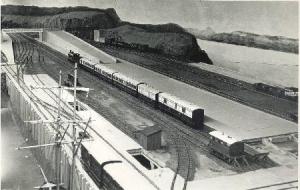
His first layout that I know anything about was when he modelled the Highland Railway and built a full sized model of Kyle of Lochalsh – weighing in at a mere 48ft. Richard was, I suspect, inspired to follow the Highland by virtue of knowing Sir Eric Hutchinson and this interest brought him into contact with my father. Although the layout was exhibited and fairly well developed as a model, Richard became conscious of some operating restrictions of the prototype (but only because he did not know that the engine shed was used as a headshunt!) and lost interest in it. He disposed of it – apparently the under-bidder was none other than Roger Daltry!
For me, however, Richard will best be associated with his layout Castle Rackrent; the name of which was inspired by a early 1970s property scandal. The origins of the layout are very modest as a small (for 7mm) transportable exhibition layout but it proved a crush in his small bedsit of the time. In an effort to find more room for the layout he found his employer accommodating (or perhaps unknowing) and erected it in a disused post office footbridge on Waverley station.
Helped perhaps by handy access during lunch breaks and the better part of a mainline station to fit it, the layout reached (I think) 70m in length before BR decided that perhaps they would like their footbridge back…… Undeterred, Richard had a house built with a conveniently large (a.k.a. giant) basement to fit it and subsequently extended it to some eight stations such that it was an entire system. The layout weaved around the room several times and even though the two stations below appeared next to each other, they were in fact nearly the length of the system apart.
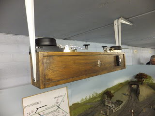
All this (or nearly all in the final incarnation) was single line and worked with bells as no station could see the adjacent station and the trains had to be driven to the signals and then handed over. This made the operation of the layout somewhat unpredictable as I discovered at one stage when I had four of the six trains on the system within my station limits and a rather irate Slim Controller (you know who you are) sending urgent telegrams to discover the whereabouts of the hunt special…….
There are rather more photographs of Castle Rackrent in my earlier blog posts – here and here. The core of the layout – Castle Rackrent itself – was exhibited widely and on some occasions quite large parts of the system was transported to shows. Here it can be seen at the Ulster Folk and Transport Museum, Cultra.
Richard’s final layout (that was completed, there were others in gestation) was Fangfoss which was built to Scale7 standards but of a 3’6″ gauge prototype in Norway. The layout was not an exact model of any location but was inspired by the Randsfjord line that was a little outside of Oslo and was a means of portaging past a series of rapids – in this case the Fangfoss.
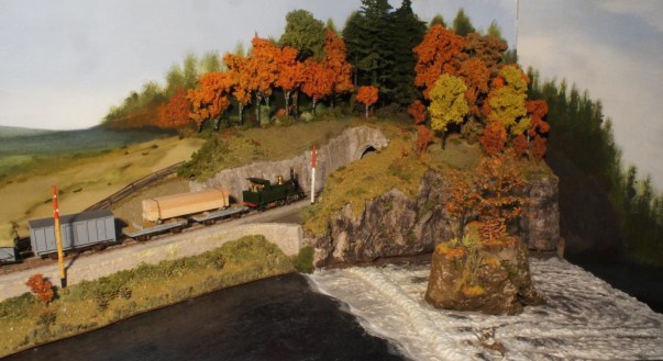
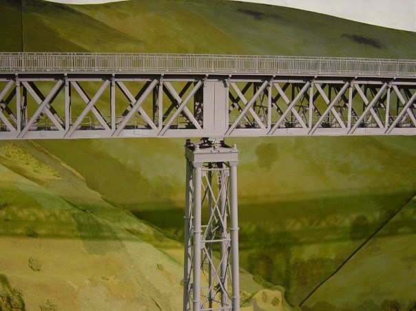
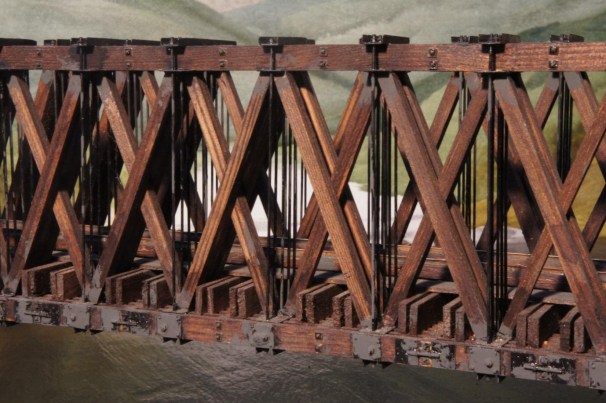
As can perhaps been seen throughout Richard’s layouts he was keenly interested in bridges, often being the key part of his models; as in Fangfoss from which this detail is taken.
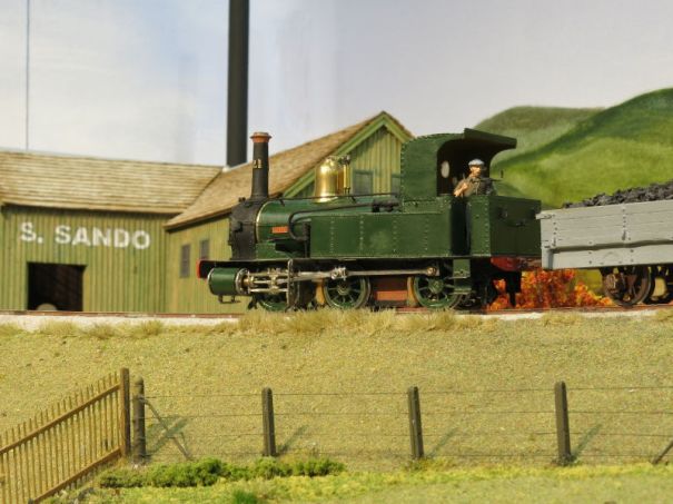
At the other extreme to the size of Kyle, Castle Rackrent or Allendenac, Richard also produced some cameo layouts, typically aimed at being transportable by train (he apparently took a large chunk of the Castle Rackrent system from Edinburgh to Bristol by train – back in the days when there were luggage compartments…..). Here is a small one called Port Lairge Wharf which was perceived as an extension of the Castle Rackrent lines (although I don’t think it was ever connected).
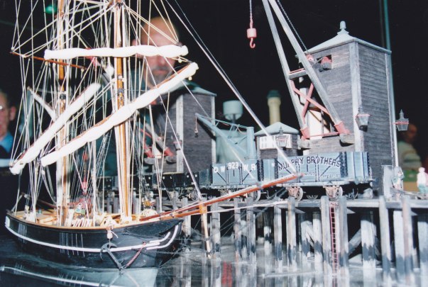
For finescale modellers in the Lothian Region, and occasional visitors from further afar like me, would gather on a monthly basis to operate Castle Rackrent and Richard was always welcoming and encouraging. He will be sorely missed by all and it is fair to say that I don’t think we will see the like of he in the hobby again…………….after all, who would try to model the tallest viaduct in the world in 7mm (even if sense did prevail on this one as it did not get completed)…….
Rest in peace, Richard.
Thanks to Jim Summers, Danny Cockling and Alan Aitken for the use of some of their photographs.
